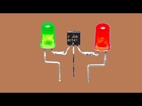
Best Electronic Project with BC547 Transistor #shorts

preview_player
Показать описание
How Transistor Work

Please like and share this video with your friends. Also, Don't forget to subscribe to our spark mind channel for more videos. Thanks for your attention.
Рекомендации по теме
Комментарии
Автор

Technical explanation: the wire basically shorts transistors base to negative terminal of battery, when he Cut the wire, base is not shorted anymore, the base emitter voltage goes up and transistor will conduct current through it’s collector and thus led, led will light up afterward.

ahmetdag
Автор

So the control wire through the resistor back to the battery is in parallel with the base pin, so the voltage is split. Therefore the voltage into the base pin isn’t great enough to overcome to junction threshold to allow current flow. Once the control wire is cut more voltage is now flowing through the base pin, enough to overcome the threshold and allow current to flow from the collector pin to the emitter pin; ‘switching on’ the transistor and turning the LED on..

currently learning some electronics through my mechanical engineering degree, am I somewhere near?

eliward
Автор

I'll just share my own explanation based on my understanding as I hope it can be helpful for someone. anyone, please feel free to correct me,   so that everyone including me can learn.
 
In this comment section, few said that a least resistance short circuit path was causing the current not to flow through the transistor hence the LED didnt illuminate, but if we carefully watch this video and draw the circuit we can identify that there isn't any such short circuit path. 
Someone in the comment section  already gave an explanation to this but was very brief. So, I would like to explain a bit further for easy understanding.

Before cutting the wire also, the current flowed through those 2 resistors but not through the LED that's why the LED didn't Light up. Why didn't the current flow through the LED? If we draw the circuit on a paper we can understand that inorder for the current to flow through the LED, it's necessary to flow thriugh the transustor as well to complete the path.But, If the transistor doesn't allow the current to flow, then current can't flow through LED aswell .It's obvious isn't it?. Now the only thing we need to check is  whether the transistor will let the current to flow through it or not. Based on the working principle of transistor, we know the Base-Emitter junction has a barrier voltage that needs to be exceeded by the external voltage supply to let the current flow through the Transistor. 
Few in the comment sectio mentioned that the battery voltage is 3.7V and the resistors are 100k and 10k ohms respectively (I didn't cross check it. Let's assume it to be correct). Since these resistors have a common junction point that is connected to the base terminal of the transistor, we can't directly say that these resistors are in series connection and simplify our calculations, because current will get divided at the junction. But the important hint we can use here is that the Base current is mostly very small so inorder to logically analyse this circuit we can approximately assume those 2 resistors as series connection and apply the voltage divider rule (Not a precise way to analyze the circuit but this approximation is helpful to understand the circuit without complications). 
So the voltage across 10k ohm resistor using voltage divider rule will be 3.7/11 = 0.336 V (when the black wire wasn't cut). Now, this Base-Emitter voltage is not enough to exceed the barrier voltage (In most cases the forward bias barrier voltage is 0.7V i.e: silicon semi conductor). So, this is why transistor isn't allowing the current flow at first. When the black wire was cut, then the Base-Emitter voltage supplied exceeds the barrier voltage and hence transistor let's current to flow through it resulting in the LED to illuminate.

subankansuthesan
Автор

If wish I had a dollar everytime someone made a yt video of making switching or blinker circuit with transistors.

mandarbamane
Автор

this is really work 😃 i made and test it

meamtown
Автор

Показано, что транзистор может быть как в закрытом, так и в открытом состоянии, в зависимости от потенциала на его базе.

MAKAR_.
Автор

My explanation : (before the wire was cut) : the positive terminal current procced through 100k resistor, after that its volt shrinks pretty much, and then it faces two paths( 1 to the transistor base, 2 to the 10k resistor which leads to the negative terminal of the battery, ) the current that goes to the transistor base is less than 0.7 volt ( which is the minimum requirement of the transistor's base to open) so negative terminal current won't be let to flow through the transistor, except if you cut the wire, by then the positive charge that had proceed the 100k resistor would only have one path to flow through which keeps its voltage undivided thus higher than 0.7 volt, then the current can flow through the transistor, turning the led on.
Was my explanation clear ?
If not so, correct me

Yousef-qfqh
Автор

Hi, what camera do you use for filming? ❤🎉

OndrejKubena
Автор

I see how the resistors save the transistor from the base, but why doesn’t the LED blow?

michaelpanelas
Автор

نفس فكره عمل الترانسيستور وممكن تخزن فيها معلومات ع هيئيه وحايد واصفار يعني الخلاصه اللي قدامكم ده كمبيوتر بسيط ❤

EbrahemAbdalla-qj
Автор

Just a friendly suggestion. Your subscribe button covers the graphics for parts in the video. Might move the graphics up jusat a bit. Love the video.

steveg
Автор

Ótimo trabalho irmão 👏 tem como fazer com um relé no mesmo circuito ?

pauloinventostube
Автор

Very simple explanation can be given for this circuit. Both the live wire and the ground were connected to the base causing it to ahort circuit. As a result the voltage at the base was zero. As soon as the black (ground) wire was disconnected, the positive voltage got applied at the base terminal causing the transistor to switch ON the circuit.

ervivekchoubey
Автор

We used to make cool things in electronics class in hs. Wish i paid more attention though now that im really interested in this. At the time i wasnt.

ElJewPacabrah
Автор

Instead of cut the wire can we add a led . Does it on

SFX__
Автор

after 6 hours of lrning abaut that now i know how this work easey

slorikser
Автор

When the circuit is complete, the LED won't lit up because the in-series resistor that is directly connected to ground (10k ohm) has the lowest voltage over it (336mV) and it isn't enough voltage to saturate the transistor. On the other hand, when the wire get cut, the voltage applied to the transistor base changes from 336mV to 3, 363V and the transistor saturates immediately.

rodrigojesi
Автор

You're welcome with lots of love and knowledge ❤️

Sanju-tk
Автор

What is the standby current consumption?

styrishrodrigues
Автор

Ok question was the wire that he cut creating a path of least resistance there for shorting the circuit? When he cut the wire it allowed current to flow through the transistor creating the path to light the bulb?

AnSTruckRepair