DIY MIDI Guitar Footswitch with Arduino

preview_player
Показать описание
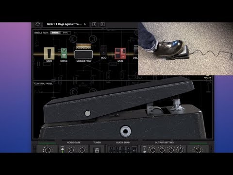
Part 2 of my DIY MIDI guitar footswitch build. In this episode I cover everything from design and component choice, to building and coding. This is my second arduino-powered MIDI controller, and pretty easy to do - and much cheaper than buying one!

Stay tuned for the next episode where I'll talk all about how I use it in Reaper - my own unique routing system for instant tone switching that works with any plugin, and any other electric or digital instrument!

**UPDATED CODE** Thanks to Michael Fischer for setting up an LED Array, this code works the same, but is a little neater and easier to expand. You can change up the pedal design fairly easily, but be sure to set up the code for your own pedal!

Schematic/Wiring images:

Parts used:

0:00-1:46 About/Demo
1:46-3:44 Design
3:44-4:26 Arduino
4:26-5:56 Build
5:56-8:06 Wiring
8:06-11:18 Code
11:18-12:56 Final Thoughts

#Arduino #MIDI #Guitar

If you want to help support this channel, buy my music on bandcamp!
____________________________________
Рекомендации по теме
Комментарии
Автор

Nice video, thanks for the content! For the input jacks reading garbage data when not connected, I would suggest using switched stereo jacks, this way the tip and ring can be both connected to ground when there's nothing plugged. I think that would solve the issue. Cheers!

fredimachadonet
Автор

I like your Project and i have an idea for a small code-improvement. Define your LEDs as Array
byte BU_LED[NUMBER_BUTTONS] = { 8, 9, 10, 11, 12, 13 };

In the setup make a loop for initalisier the LEDs:
for (byte n = 0; n <= NUMBER_BUTTONS; n++) {
pinMode(BU_LED[n], OUTPUT);
}

And in the big "case 2:" make a loop to turn all LED of and then the "i" LED on.
for (byte n = 0; n <= NUMBER_BUTTONS; n++) {
digitalWrite(BU_LED[n], LOW);
}
digitalWrite(BU_LED[i], HIGH);

So it is easyer to make changes for a 8-Button-Footswitch. Only make NUMBER_BUTTONS=8 and add 2 numbers in the array.
If you want you can make a sepate NUMBER_LEDS constant for better readable.
I can't test the code, because i have no arduino right now. But if you have trouble i like to help. I'm not a native speaker but i hope you understand.

Michael_Fischer
Автор

Nice video! I'm in the process of building a similar enclosure. My plan is to do what you did here and also have a bunch of loops that i can select and have a physical pedal in each loop and therefore i could use different physical overdrives with different amp modelers/pluggins in my DAW.
In your video you said at one point that in the code you use a bunch of if/else statements and that you would welcome alternatives to that... For that type of scenario it's often better to use a Switch (case) statement, the reason being the value of the "case" will be evaluated first and the branching will be made in regards to that, vs the if/else method, every statement will be evaluated in the order that they have been written until a match is found, so the last one would take more time to reach. If you choose to use a Switch statement, don't forget to include a break at the end of each case.
the syntax would be something like this:

switch (i) {

case 0:
digitalWrite(BU1LED, HIGH);
digitalWrite(BU2LED, LOW);
digitalWrite(BU3LED, LOW);
digitalWrite(BU4LED, LOW);
digitalWrite(BU5LED, LOW);
digitalWrite(BU6LED, LOW);
break;

case 1:
digitalWrite(BU1LED, LOW);
digitalWrite(BU2LED, HIGH);
digitalWrite(BU3LED, LOW);
digitalWrite(BU4LED, LOW);
digitalWrite(BU5LED, LOW);
digitalWrite(BU6LED, LOW);
break;

(...)

default:
// statements
break;
}

lpblewis
Автор

BRUH, Thank you. I'm a tinkerer who just got back into playing guitar after about 10 years. I've been trying to find a way to use an expression pedal with my computer for my amp sims pedal boards and such, but all my options were adapter boxes that cost like 100 bucks, or a keyboard that'd take one over MIDI. I was worried this wouldn't do expression at first, so glad to see it does as well!

jackbootshamangaming
Автор

Can wait the project with add switch for bank selector,
Cool project.

manday_
Автор

Nice. I built mine to control PA600 arranger keyboard .16 buttins. 5 to select key signature. 7 chord changes (I, IV, V, II, ii, vi, iii) 4 rhythm variations, ending, fadeout, and inteo.
I can sing and guitar while controlling backing tracks.

jonk
Автор

This ia a really cool and interesting project. Thanks for taking the time to run through it.
You give great crab!
cheers mate

FlyingBystander
Автор

HI.
This is a great project.

I challenged this.

I modified the source a bit and it worked with Zoom MS70 CDR.

I stopped using LEDs. Because the second LED (D9) didn't light up.

Zoom MS70CDR is equipped with a display, so it doesn't matter if you don't have an LED.

Thanks for sharing this video.🤘

SyusakuSano
Автор

This looks awesome, I'm gonna have to try this, thank you!

CameronWinters
Автор

Hi. I’m trying to do the same device. I use the LGT8F328P controller. This is an analogue of the Arduino Nano and the firmware sketch should fit. I built a prototype on your schematic, downloaded your archive, firmware uploaded to the microcontroler without problems or errors, but nothing worked. What version of MIDI_Library did you use? And how exactly do you connect your MIDI CRAB to your computer? I have a computer with Windows 10. I understand in order to make the device work to create a virtual midi port on the computer using software. I tried to use Serial_MIDI_Converter and loopMidi, but it didn’t work. Maybe I’m doing something wrong. I would be very happy if you would answer.

ДенисКораблёв-гт
Автор

Im thinking of making since most availble to buy has buttons too close together so I often misstep in a live situation....
I would like to have only 4-5 buttons but with bigger space between.
Two rows, lower with 3 for the sounds I use for the most part, and 2 on top with some patches I only use occasional.

I will have this video in mind

BlazonStone
Автор

Hi Nick!, this is awesome planning on building my own foot switch, question is what if I Decided to add expression pedal? do I need to buy a separate arduino?

lawrenzescover
Автор

hi Nick! excellent video, its a very nice project! The footswitch is plug and play? How did you configure the controller so that it is a MIDI controller and is recognized in different software such as ableton? thank you very much!

youAlvaroGonz
Автор

I'm trying to build one strictly for punch in/out and return to start, just to keep my hands on the guitar. I hear those Teensy controllers are much easier, but I have Nanos and and Uno already so all I would need is the box/switches which are cheap. Anyway, great build and thanks for the rundown/code.

minkorrh
Автор

Cool project!!
I can't find the connection diagram, can you share it?

iks
Автор

For all those who are new to this and really want a footswitch so that they can change effects and presets, here is a quick complete guide answering all your questions.

What you need -
1. A box, it can be of plastic or metal( you can also use any old box that you have lying around, I used an old DTH box, removed everything from inside and saved up my money). Electric boxes like the Hammond one used in the video is rarely available in my country and I was hesitant to use a plastic box, so I went with the dusty old DTH box

2. A microcontroller - there are tons of microcontrollers out there, some are midi compliant while others are not. For example- The teensy LC is a midi class compliant microcontroller and can be used very easily, you can find the whole tutorial on YouTube. However using the most common microcontroller like the Arduino Uno is also possible, you would have to run 2 applications (mentioned in the video) while using the footswitch that's it. The most difficult task was choosing the microcontroller for me in my journey of building the footswitch, because I was not able to figure out how to use my UNO for the project, but the code provided in the video is sufficient and directly copy pasting it in Arduino IDE works just fine. I put electrical tape on the exposed parts of UNO to avoid shorting of the components.

3. Buttons - In my country the stompbox SPST switches were not available, they had to be imported and it would cost me around 30 bucks for the switches alone, I used normal SPST Momentary Switch that students generally use for their science projects, it works perfectly but the only downside is that they are smaller than regular stompbox switches, it only cost me around 2.5 dollars for 5 switches.

Wiring - You don't need to solder, it's optional, you can use hookup wire for the Daisy chain as mentioned in the video video or just use the breadboard wire, to join everything you can use gluegun to keep the wires in place.

Only 3 things are required, the rest is optional but highly recommended.

4. An expression pedal - I had to buy and expression pedal for this project ( got the M- Audio expression pedal), it is a little costly in my country but there are several workarounds with volume pedals that are quite cheaper, and you can use a volume pedal as expression pedal in some cases, controlling various parameters other than volume.

5. Barrel Jack - there are two options- either go with the Marshall sized barrel jack ( which is only available in bulk quantities in my country, a single jack is again costly in my region) or go with a 3.5mm stereo jack module that would even cost less than a dollar. You can then use a 3.5mm male to 6.3mm female adaptor to make it work like a regular one. You can attach multiple jacks if you want by editing the code. However I have only used one.

The whole project cost me around 25 bucks, where I also got the expression pedal. My friend had an uno and some wires lying around that he had no use for so I borrowed it from him.

6. LED's - Optional, I haven't used any led to keep my project simple and avoiding a bird's nest inside the box xD

Now for the most important part, the footswitch can work with almost every daw out there like FL Studio, Ableton etc. Setting up your foot switch is easy and again you can find tutorials for it.

For example I use Bias FX2 and Neural DSP, both support midi commanders and it's easy to set it up. It will also work with Amplitube and Guitar rig 6, no need to worry

The footswitch can control any parameter that you assign it to, adding more switches increases the flexibility of use.

My advise is to not buy midi footswitches ( or almost any other midi device that's out there, cause you can build them yourself and make it look as a retail unit) that go for around 100-150 US dollars, build one yourself it will only take you 2-3 hours to build one, my whole project got wrapped up in less than 25 dollars.

Other MIDI devices- I'm a guitarist and I don't have an amp at all, I only have my audio interface with me and I use a 10w speaker for the audio output. Changing knobs on my software can be quite irritating sometimes, you can also build a midi controller to change the knobs by using potentiometers, the options are endless. It can look very difficult at first but trust me, once I made the footswitch work it gave me a sense of accomplishment and I got a idea of how Arduino works.

I guess that I have covered as many issues that generally people face, if anyone has any other question they can ask me in the comments and I'll surely reply! Peace and good luck on nailing down your first Arduino project✌️

aryanchhajer
Автор

Hi, that is such a nice project!

I dont wanna use the leds, so, just removing that part of the code would work? And I will use an esp32 as controller, if it works I’ll give feedback

rodolphonetto
Автор

Great stuff man, i'm planning of doing one of these for guitar playing with vst plugins. Are you connecting a normal expression pedal to the stereo jacks?

aletondaX
Автор

hey you gave me the idea to make little modules to turn my pedals on or off like the G Lab Uproar Fuzz does

Funkodelics
Автор

HI Nick good day tried to follow all steps provided on video, but after uploading the code to my arduino reaper/amplitube 5 cant detect or midi is not showing do you have any inputs for this? thank you!

RodrickWalker-ve