filmov
tv
#270 AM Radio DIY kit

Показать описание
episode 270
building and testing a 7 transistor AM radio kit
Be a Patron:
building and testing a 7 transistor AM radio kit
Be a Patron:
 0:25:49
#270 AM Radio DIY kit
 0:23:08
Modding the Murania AM Radio Kit
 0:29:07
Murania AM Radio Kit Build & Review
 0:41:35
CF210SP AM/FM Radio Kit Build
 0:20:03
Taobao BS208 AM FM DIY Kit Radio
 0:26:22
Assembling the Chinese CF210SP AM FM Radio Kit
 0:15:12
How to make CRYSTAL RADIO
 0:21:32
Elenco AM-780K AM Radio Kit Build and Review
 0:21:58
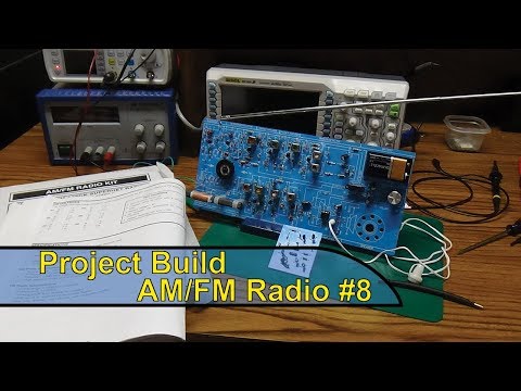
Build - Radio Kit #8 (RF Amplifier, Antenna)
 0:13:12
Diy Kit HX108-2 AM Radio Electronic Assemble Set Am @zero-zone420
 0:08:29
Boshi Banggood AM Radio Kit Build
 2:00:47
HX 108-2 am kit radio assembly alignment and test
 0:05:40
Мелкий FM-радиоприёмник Aitexm AK-270 | DIY KIT набор для самостоятельной сборки | #Обзор...
 0:08:12
DIY Kit CF210SP AM FM Stereo Radio Electronic Assemble Set FM 76MHz 108MHz part1
 0:18:08
COMPLETE PORTABLE RADIO KIT (updated)
 0:32:55
Vogurtime VT-08 AM/FM Radio Kit Build
 0:09:58
FM AM Радио BS 208 HAF Радиоконструктор
 0:00:13
Their Boat Engine Fell Off
 0:02:02
DIY Kit FM Радиоприемник собери сам
 0:14:16
ZX921 AM Radio lookover
 0:11:39
HX 6B AM Radio Kit eBay
 0:00:35
ČRo Radiožurnál 270 kHz,Topolná, Czech Republic on a long wave crystal radio in UK
 0:00:05
Don't make eye contact
 0:34:30
#243 AM Transmitter - Power Supply Build
Комментарии