filmov
tv
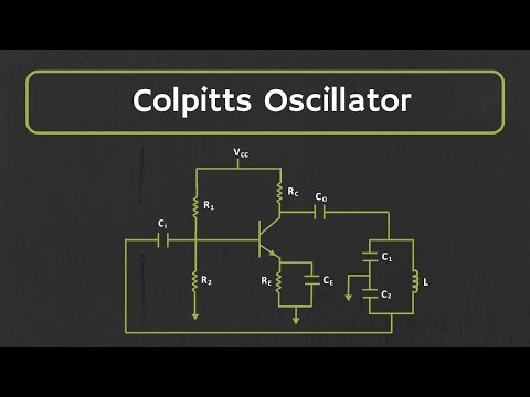
Colpitts Oscillator Circuit Analysis (7 - Oscillators)

Показать описание
Let's design a radio frequency Colpitts Oscillator together. We'll be using a common-emitter configuration bipolar transistor.
Aaron Danner is a professor in the Department of Electrical and Computer Engineering at the National University of Singapore.
Video filmed and edited by Cheryl Lim.
@randomcheryl
Aaron Danner is a professor in the Department of Electrical and Computer Engineering at the National University of Singapore.
Video filmed and edited by Cheryl Lim.
@randomcheryl
 0:11:05
Colpitts Oscillator Circuit Analysis (7 - Oscillators)
 0:15:39
Colpits and Hartley Oscillators - Solid-state Devices and Analog Circuits - Day 6, Part 7
 0:00:07
How Colpitts Crystal Oscillator Works in Electronics
 0:17:38
Colpitts Oscillator Explained
 0:14:14
How Colpitts Oscillators Work - DC To Daylight
 0:00:56
Colpitts Oscillator Circuit - Using a transistor (Electronics 101)
 0:00:05
Basics of COLPITTS OSCILLATOR 💡 #shorts #youtubeshorts #electrical #electronics #powerelectronics
 0:05:34
Demonstration and Discussion of Colpitts Oscillator (8 - Oscillators)
 0:05:42
Colpitts Oscillator
 0:00:46
Colpitts oscillator , 7 MHz , 40 m band
 0:00:16
Hartley Oscillator
 0:02:09
Electronics: JFET colpitts oscillator - very unstable (2 Solutions!!)
 0:00:11
Tunable Colpitt's Oscillator 2.0
 0:28:56
#96: Analysis & Design of a Typical Colpitts Oscillator
 0:11:15
Colpit's oscillator
 0:04:20
Colpitts Oscillator
 0:00:14
Colpitts oscillator. 3D rendered PCB model
 0:05:49
Colpitt's Oscillator (Analog Circuits)
 0:01:20
Colpitts Oscillator #oscillator #oscillations #oscillating
 0:00:05
Basics of Colpitt's oscillator💡 #shorts #youtubeshorts #electrical #electronics #education #eee...
 0:01:45
Electronics: How to increase the amplitude of a colpitts oscillator circuit? (2 Solutions!!)
 0:22:22
Drain Feedback E MOSFET Colpitts Oscillator Design
 0:00:06
Colpitts oscillator
 0:04:11
PRODUCE 1MHz SIGNAL USING COLPITTS OSCILLATOR CIRCUIT 2BEEZ
Комментарии