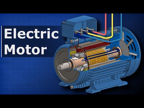
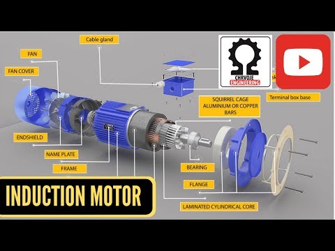
Induction Motor - Explained

preview_player
Показать описание
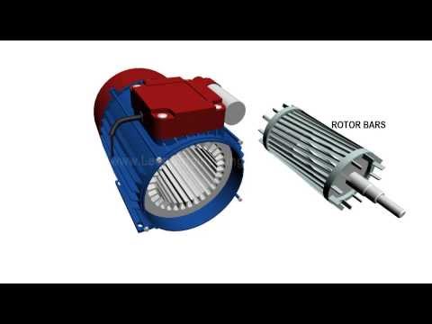
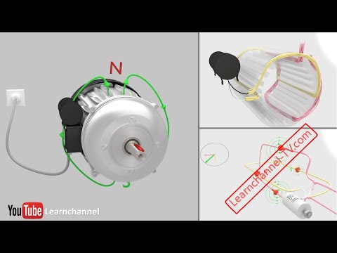
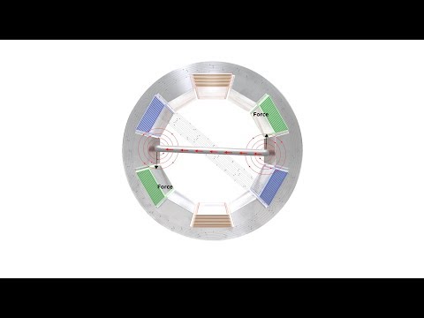
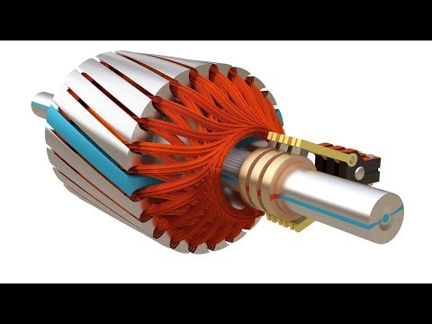
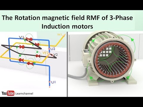
What is an induction motor? How do induction motors work? Induction motors induce a current into an electromagnetic rotor in order to create rotation. This is done by using alternating currents to create a rotating magnetic field. The number of alternating currents can vary. A three phase AC motor uses 3 alternating currents out of phase, to create rotating electromagnets.

-- Related Videos --

Please feel free to rate, comment, and subscribe!
And don't forget to check out my Facebook page:

Also check out my official website: Make suggestions, participate in forums, learn through logically ordered lessons, read FAQs, and plan your future!

Now on Twitter:

NEW VIDEO EVERY WEDNESDAY!
Рекомендации по теме
Комментарии
Автор

This was a great way of confirming the ideas I already had from a lecture. Very well explained, thank you!

captain_bretzel
Автор

Even without watching the prerequisite videos, this still was pretty easy to understand. Thank you for your clear explanation!

alkankondo
Автор

This video has helped me so many times when studying for exams. Thank you!

patrickdunstan
Автор

Nice diagrams, but unfortunately you seem to have described something similar to a "stepper motor" (where-by the iron "rotor" rotates to align its two ends with the "N" and "S" poles of the "stator", and thereby maximises the "magnetic-flux-density" by minimising the reluctance across the two air-gaps, (by making the rotor to stator gaps minimum. )

Agreeably, as you explain, the (two-phase, and ideally 3-phase) "induction-motor" DOES produce a "magnetic-field" rotating around the circumference of the fixed stator (typically two "north-poles" and two "south-south" poles in a Rear-wheel drive Tesla Model-S 90 induction-motor containing 60 "stator" teeth (around which phase wires are wrapped) and 74 rotor teeth (between which a "squirrel-cage" of solid copper bars are laid) see Tesla (pending) patent EP2202871 A3), BUT the rotor is essentially several low-resistance conducting wires or bars (typically NON-magnetic copper) ideally arranged VERY CLOSE TO THE SURFACE of the rotor's circumference (and parallel to the rotor axis), and not, as you seem to show, wound radially along the diameter of the rotor.
The torque on the rotor is then developed by the interaction between the "magnetic-flux-density" ("B" teslas) which exists in the "stator's" "magnetic-field", and the electric-current ("I" amps) flowing along most of the "rotor's" copper bars. The really elegant thing about the induction-motor, is the way the the electric-current is produced in the rotor (without the need for brushes or slip-rings), and is usually the tricky bit to understanding how induction motors work:-
Essentially NO electric-current (and therefore NO torque) is "created WHILE the "rotor" is rotating at the SAME "rotation rate" (eg rpm) as the magnetic-field in the "stator" ! Only while the "rotor" is NOT RUNNING SYNCHRONOUS with the "stator's" magnetic-field, (ie the "rotor" is rotating slower (or conversly faster) than the "stator's" rotating field) IS "electric-current" (OR STRICTLY A VOLTAGE CALLED "EMF") "INDUCED" into the copper bars, (hence the induction motor is also known as an "asynchronous" (assynchronous?) motor).
The "EMF voltage" (and therefore the "electric-current") is induced in the copper-bars only while each copper-bar experiences a CHANGING "magnetic-flux-density" (because each looping "magnetic-field line" (moving faster (or conversly slower) around (and beyond) the stator) is moving across each copper bar).
The rotor (and hence the elecric car) will accelerate by using sophisticated electronics to rotate the "magnetic-field-lines" (around the stationary "stator") faster than the copper bars (in the "rotor"), or conversly cause a braking-deceleration by rotating the "magnetic-field-lines" slower than the copper bars!
See the excellent "Electric Motors and Drives" by Austin Hughes 3rd/4th Ed, for beautiful motor descriptions with the minimum of mathematics involved !

paulrhodes
Автор

Nice job bro. Using this to help an intro (very intro) Emag class I'm teaching. Well done.

hnmcclain
Автор

Always awesome explanations. I feel in the know now, thanks!

twoelevenscho
Автор

Great watching your videos. Very clear and educational dude!

martinhernanzorkendorfer
Автор

it is never complicated when you explain 'em!

zee
Автор

please make videos on the new technology that are coming in automobiles....

amritbhowmick
Автор

awesome job..really appreciate it..would love if you can make induction generator video..thanks

aqm
Автор

I am not sure if the rotor is actually trying to magnetically lock up with the rotating magnetic field. Because that would make the slip zero and cause no more rotation. I have read it somewhere that its because of Lenz's law, the rotor is rotating. According to Lenz's law, the induced current will cause an effect that would work against the field that created it. To negate the field, the induced current is causing the rotor to rotate and thereby trying to cancel the relative motion which thereby cancels the induction. But i am not sure either.

rparamban
Автор

Great video! Helped me understand how these work. The one aspect I'm still having difficulty understanding is speed control.

It seems to me based on your explanation the frequency of the AC current supplied is what dictates the rotor speed. I've always assumed 60hertz was a standard frequency for AC current. Can you or someone please explain how the speed is actually regulated by voltage? or current? or frequency?

joechavez
Автор

Hi, I really do enjoy your fine explanations on how car related stuff work, and i thank you very much for that, i would be grateful if you could explain the hydraulic details about the ESP, EBD and ABS and how they operate together. thanks    

chaharshanbe
Автор

how many brushless cordless drills do I need to make a decent Honda Civic swap?

jameslangstonevans
Автор

I think you should start to get more appealing content into your videos like you have done, but you have already covered a lot of the stuff! Still great Videos as they have always been!

tekamstheone
Автор

HEY THIS IS A VERY HELPFUL VIDEO THANK YOU VERY MUCH ! but i have one question, for my project im supposed to make an induction motor, the other videos i've watched they used cans, disks, etc as the "rotor", could you explain how they used that instead of a coils

jamalDougie
Автор

Love your videos! Could you go more in depth on this topic? It is becoming more relevant now that a lot of EVs are coming to market.

kodez
Автор

I understand changing the polarity of the stator through the coils is what get the central rotor spinning. But my question is, If the coil is permanently attached to the battery, how does it (the battery) control or regulate this current, how does the battery changes on/off to affect the polarity of the stator if its wires are connected all the time

jdanielortega
Автор

This is a great video, will you go further into AC motors next week? 

DJAlsip
Автор

Maybe explain Pulse Width Modulation seeing as how it is used to control the speed of brushless motors (and probably Induction motors too?)

corydiesel