filmov
tv
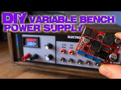
DIY Variable Lab Bench Power Supply from ATX - How to Make it Cheap

Показать описание
In this video I will show you how I created a Variable Laboratory Power Supply from a computer ATX. Don't throw these PSUs away! These can be very useful for any electrical project. The whole power supply is very cheap, no more than 10$. The main unit of the device is a ZK-4KX Buck-Boost converter module, that is adjustable in 0.5-30 V and 0-4 A range. Additionally you will need some basic components only.
******************************************
Background music:
Track 1: Lensko - Cetus [NCS Release]
Music provided by NoCopyrightSounds
Track 2: Disfigure - Blank [NCS Release]
Music provided by NoCopyrightSounds
Track 3: Different Heaven - Nekozilla [NCS Release]
Music provided by NoCopyrightSounds
******************************************
Background music:
Track 1: Lensko - Cetus [NCS Release]
Music provided by NoCopyrightSounds
Track 2: Disfigure - Blank [NCS Release]
Music provided by NoCopyrightSounds
Track 3: Different Heaven - Nekozilla [NCS Release]
Music provided by NoCopyrightSounds
 0:07:10
Build your own Variable Lab Bench Power Supply
 0:12:12
DIY Variable Lab Bench Power Supply - 3D Print & XY-SK35H Module
 0:05:29
Diy Variable Lab Bench Power Supply | 220v/110v to 20A Power Supply.
 0:20:06
Build the Ultimate Bench Power Supply for Electronics
 0:11:09
DIY variable bench power supply (less than 10$)
 0:12:57
ATX conversion to bench power supply (fixed & variable)
 0:11:12
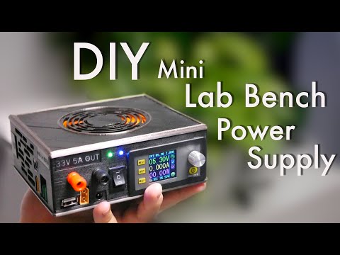
DIY Mini Lab Bench Power Supply (With Switchable DC and AC Input)
 0:15:53
DIY Dual Channel Variable Lab Bench Power Supply 30V 10A 260W Build & Test
 0:05:18
Mini Variable DC Bench Power Supply 4.5Amps DIY
 0:02:27
Is This Bench Power Supply Any Good? #powersupply #productreview
 0:16:42
DIY Variable Bench Power Supply 50V, 5A Using ATX Power Supply & WZ5005 module Joule Works
 0:10:48
DIY Mini Lab Power Supply | Battery Charger | Constant Current LED Driver
 0:07:14
Bench Power Supply vs ATX
 0:10:25
Affordable variable bench power supply - with external power source
 0:13:20
Small Bench DC Power Supplies - Review and How To (Constant Current vs. Constant Voltage)
 0:10:23
DIY Variable Lab Bench Power Supply from ATX - How to Make it Cheap
 0:19:28
DIY Variable Lab Bench Power Supply
 0:23:47
4 HOMEMADE Bench Power Supply LOW COST
 0:13:20
WOW! Amazing DIY Variable Lab Bench Power Supply
 1:12:39
Linear DC Power Supplies - Designing & Building Custom DC Power Supplies
 0:22:42
EEVblog #1030 - $20 DIY Bench Power Supply!
 0:38:04
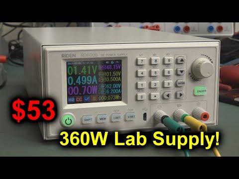
EEVblog #1265 - $53 360W Lab Bench PSU!
 0:26:07
The Ultimate DIY Variable Lab Bench Power Supply
 0:09:43
Do Not Use Cheap Variable DC Bench Power Supply until you do this
Комментарии