filmov
tv
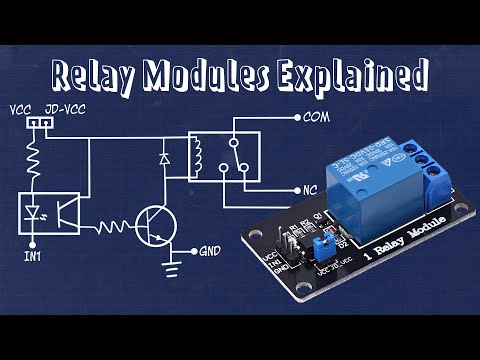
Connecting a Relay Module to a Microcontroller

Показать описание
Today we are driving high current high voltage applications using only a microcontroller and relay. To accomplish this, we are going to take a closer look at a few different types of relay modules you might find across the Internet. We will first go over the components and connections available on each module, then we will go over the schematic to get a better understanding of how each module works, and finally we will demonstrate how to connect these modules into our circuits. Throughout this video I will touch on important considerations to mindful of to ensure you don’t damage your microcontroller or worse the item connected to the relay.
00:00 Intro
00:39 Hardware Overview
02:56 Relay One Schematic
06:22 Relay Two Schematic
07:53 Relay Three Schematic
08:20 Demo with External Power Supply
09:52 Demo without External Power Supply
11:19 Recap
Hardware:
Helpful Links:
00:00 Intro
00:39 Hardware Overview
02:56 Relay One Schematic
06:22 Relay Two Schematic
07:53 Relay Three Schematic
08:20 Demo with External Power Supply
09:52 Demo without External Power Supply
11:19 Recap
Hardware:
Helpful Links:
 0:11:41
Connecting a Relay Module to a Microcontroller
 0:05:02
What is Relay? | How to control Relay using Arduino
 0:04:41
How to use an Arduino Relay Module
 0:00:38
5v relay module connection #shorts #shortvideo #youtubeshorts #spdt #electricalteluguvideos
 0:00:18
5V 8 Channel Relay Module For Arduino from banggood.com
 0:22:48
Everything you need to know about RELAYS
 0:05:07
MY2N Glass Relay Connection With Sensor @the electrical guy
 0:06:18
5 volt relay module switched by either high or low input signal how to DIY demonstration
 0:07:30
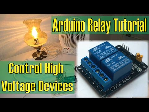
Control High Voltage Devices – Arduino Relay Tutorial
 0:04:56
Using 5V 1 channel relay module for Arduino
 0:11:51
How to use 2 channel relay to control AC and DC loads in Arduino
 0:04:49
How to connect a relay with PLC || Complete guide || PLC Programming Tutorials for Beginners
 0:00:17
Arduino - Driving DC Motor (Water Pump) with Relay
 0:11:23
Electronics 12V relay with dual NC NO switches module with high or low trigger
 0:01:55
How to Wire a Relay Module for a Raspberry Pi
 0:02:45
How to connect a 2 Way Relais Module with the arduino
 0:16:52
#18 Add a Relay Module to your Arduino project - Hints, Tips & Traps
 0:05:11
HOW TO INTERFACE 5V 4 CHANNEL RELAY MODULE WITH ARDUINO
 0:11:36
HOW TO USE RELAY MODULE WITH ARDUINO | 4 RELAY MODULE ARDUINO | RELAY MODULE | 5V RELAY MODULE
 0:02:40
How To Wire A Relay - Quick Tip
 0:06:11
5volt Relay Module connection || all Sensor Module use | Electronics Verma
 0:03:13
Connect a Relay Module to NodeMCU
 0:01:35
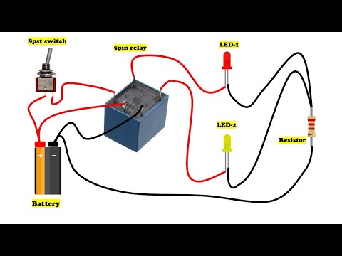
5 pin relay wiring diagram
 0:06:20
How to test 5VDC relay module
Комментарии