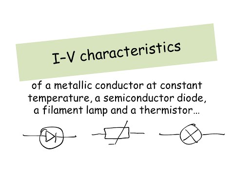
GCE (A level) Physics E06 IV (Characteristic) Curves Diodes Part 2 of 2 (diodes)

preview_player
Показать описание
Second part of a 2 part lesson introducing the IV curve, sometimes called the current voltage curve or characteristic curve. Explains what a diode is and its characterisitic (IV) curve. Also describes circuits which can be used for IV curve measurement.
Рекомендации по теме
Комментарии
Автор

very high quality videos, thanks for your effort in educating people.

gene
Автор

Hi. I'm pleased the videos are useful.
For many situations, it is accurate enough to say that a diode ‘only conducts in one direction’. That’s because when a diode is reverse biased, the current is usually small enough to be ignored - maybe only a few micro-amps. The reverse-biased diode has a very high resistance (providing there is no breakdown).
But if we are being accurate, we CAN measure the reverse-bias current; it is small but not zero.
Hope that helps and good luck with the exams.

StevePhysics
Автор

I have my OCR AS physics exam coming up tomorrow and I'm awake at 5am. Why didn't I discover your videos earlier!?!?!? So helpful! Oh well, praying for 300UMS

Halfdead
Автор

Yes, an ideal diode has zero forward resistance and infinite reverse resistance, so it’s a perfect ‘1-way valve’. I don’t use the term ‘ideal’ but the introductory material (required for some A-level syllabuses) treats the diode’s behaviour as ideal. The video then looks at things more carefully and deals with characteristics of ’real’ diodes, including leakage and breakdown, (also required by some A-level syllabuses). Please let me know if you think there is something wrong.

StevePhysics
Автор

I know!! the same thing happened when I had my Physics GCSE exam in the morning, I was revising and then found out that there was a thing called 'Khanacademy', which now I am finding useful for all my subjects for As level.

Hope you get your 300UMS

Unted-Kingdom
Автор

The statement ‘diodes only conduct in one direction’ is a convenient simplification, which is often made. It is inaccurate but is an adequate way of thinking about diodes for most simple applications. This is because the leakage current is usually negligible, and because diodes are seldom operated at or near breakdown (except for Zener diodes which are outside the scope of the lesson). I cover both leakage and breakdown currents in the video (from about 6mins40s). Hope that helps.

StevePhysics
Автор

Than you so much for your videos. I had no hope in physics but after seeing your videos I'm hoping to ace my AS exams which is in less than 2 weeks. One question though, dosen't a diode conduct electicity in one direction ? So how is the reversed bias graph not zero ?ho come there is a voltage and current ?

senzywenzy
Автор

Thank you so much!!! I've been searching all over the place for a thorough explanation of how I-V Curves work. I did watch the other part, so I'm going to post this same comment there too :) :) :) :)

ejrashad
Автор

Here is a short but VERY oversimplified explanation.

There is region at the boundary between the p and n type materials in the diode called the depletion layer. The depletion layer acts as a barrier to current. Applying a forward voltage reduces the thickness of the depletion layer until (at 0.7V) it effectively vanishes. This is a bit like opening floodgates and the current rapidly increases.

For a better explanation, just do a search on ‘how a p-n junction works’.

StevePhysics
Автор

Do you know why diodes start off with little or no voltage as current increases?

MissAjayG
Автор

Excellent video Steve! I have a question if you would be so kind. I came across a question where you were given IV characteristic of a diode and asked to explain why the temperature of the semiconductor increases. What I am confused with is that the markscheme only allowed answers talking about an increase in current causing the temperature rise and only gave credit for using P = I^2R. It strictly gave no credit for talking about increasing voltage causing the increase in temperature.

In transmission lines I get why you can only use P = I^2R because there is little/no voltage drop to the transmission lines as it is all lost at the load hence current becomes the only factor determining temperature rise. But if you have an IV characteristic for a diode there IS a voltage drop and it is being increased so surely both P = I^2R and P = V^2/R are valid here. Otherwise, we are saying voltage is increasing which means power being delivered to the device is increasing yet we are saying temperature isn't increasing because of this? Thanks.

Alfster
Автор

damn the comments are so old! Your videos still help ppl :)

mushroomravioli
Автор

@MissAjayG
Hi. The reason is quite complex. A diode basically consist an n-type material and a p-type material. The current-voltage relationship depends what happens at the boundary (junction) between these two types of material. There isn't enough space to fit a proper explanation in here, so I've sent you an email with a bit more information.

StevePhysics
Автор

Hi. I know it is in the AQA GCE Physics A syllabus (in Unit 1 PHYA1 Particles, Quantum Phenomena and Electricity). But I don't know about other syllabuses.
You will need to check the Examination Board syllabus you are using. There are quite a few different Examination Boards and often more than 1 syllabus per Board. Each syllabus covers different material.
If you go online, and find whichever syllabus you are using, you can search for ‘diode’ and check. Sorry I can't help more.

StevePhysics
Автор

@valentine8vdogg
Hi. I don’t have (or plan) a video on diodes in parallel. This isn’t really a ‘topic’. You work out such problems by applying your basic knowledge to the circuit in question.
For example, in simple terms, if 2 diodes are in parallel, one will conduct when the other doesn’t. A more detailed calculation taking into account the characteristic curve would be more complicated and more ‘electronic engineering’ than basic physics.

StevePhysics
Автор

Not realistic at all! If you measure this way, your diode will be blown up immediately! There has to be a current limiting resistor in series with the diode at all times!

koenvandemoortel