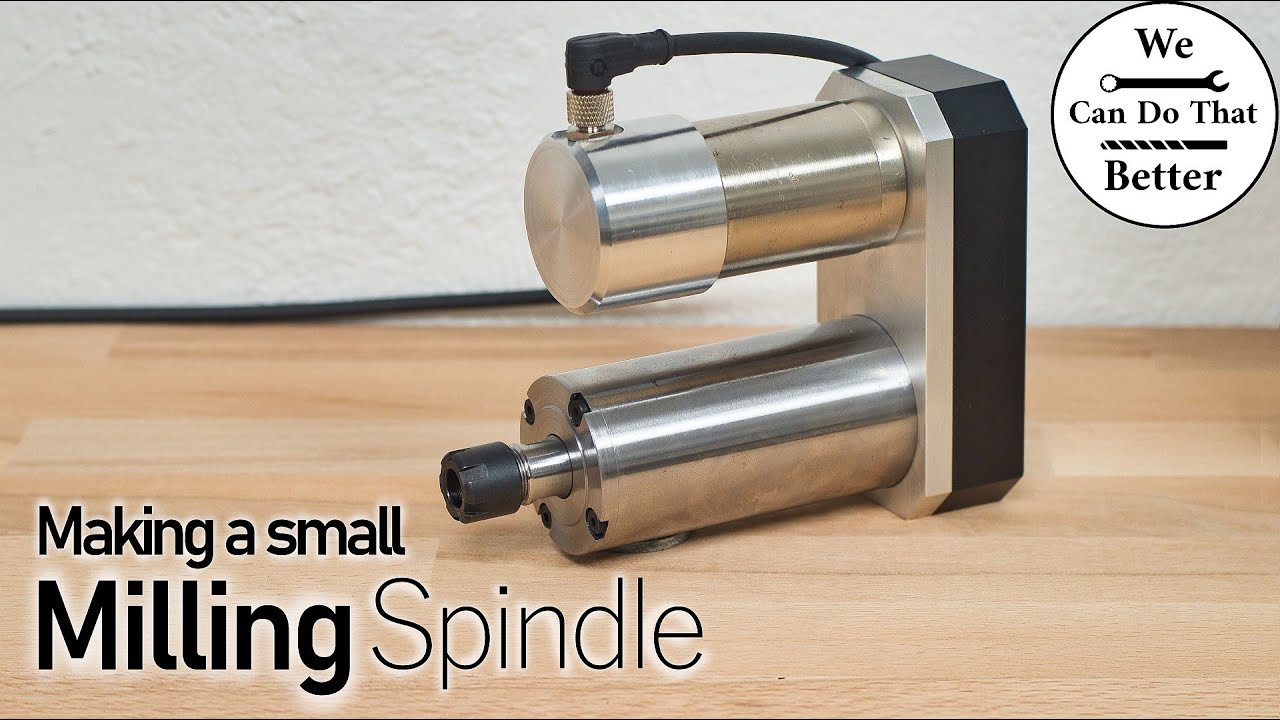
Homemade Micro Milling Spindle

preview_player
Показать описание

For a futur project I need a small milling spindle. Inspired by the article above I started to build my own one. I used an ER-11 collet extension, 7200 angular contact bearings, a piece of 40mm ground C45 round steel for the spindle housing and an Escap 32V motor for the drive. Unfortunately I could only find the servo version of this motor which has some extra encoder stuff mounted on the rear side. I removed all this but it seems that this was not the best thing for the motor. After the modification it ran not as smooth as before. So if someone has the normal Escap 35NT for me, don't hesitate to contact me :)
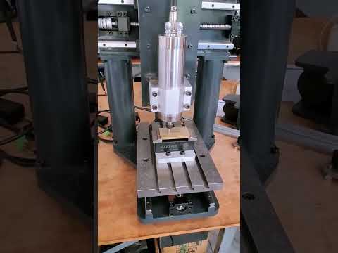
After the first tests the spindle seems to work quite fine. I just have to make the poly-V pulleys a little bit smaller as the belt rubs against the inside of the belt cover.
This spindle might also be used as a toolpost grinder. I guess it is not that big of a difference.

I hope you enjoy the build and the video. It is a little bit on the long side.
Let me know what you think about it.
If you have questions or suggestions feel free to comment below.

If you are interested in more DIY toolmaking and machining stuff with budget equipment, consider subscribing to the channel. I really do appreciate your support.

Thanks.

Рекомендации по теме
Комментарии
Автор

I tried to start my own channel recently. Now I know how hard it is and how quality this content is. Great job, thank you!

danielross
Автор

Ooof, ripped the encoder off!

That spindle encoder would have saved you some grief later - common to use one on small spindles because keeping the right RPM means keeping chip load correct, and those little spindle bog down pretty easily.

This leads to the chip load getting out of hand, and soon you're deflecting your little miller too much and breaking them all the time, despite using a really slow feed: Too slow and you're rubbing, and not enough heat is taken away because the chip is too small. There's a narrow optimal chip load which is as thick as you can do, given the situation, limited by tool deflection upwards, and keeping this requires the spindle speed to not change as the cutter engages and disengages... which changes load on the motor, and without speed feedback, WILL cause the speed to dip, or else be too high when the chip is thin.

Best you can do is get the speeds and feeds right for the cut, there are calculators for this specficially super useful for small spindles, because the small bits are so easy to break.
But yeah - should have left the encoder on, because using it for feedback to keep the spindle at the programmed RPM is absolutely something you'll later miss.

Which speeds and feeds are optimal seems to be something this machinist isn't aware of - just going a little faster can in some cases fix chatter and lead to a better surface finish: What you're doing is avoiding a mechanical resonance. It's counterintuitive that cutting faster and deeper would do this, but it does. And this matters even more for ER11's.

RGDk
Автор

That little brass insert in the lock nut was genius.

Bloodray
Автор

A very useful little gizmo, the comments show how this could be improved in detail, thanks for publishing the video which provides inspiration for those of us who would like something similar 😊

pcka
Автор

That is something! At first, I didn’t realize that there was a lot of work involved in building since I really didn’t know what it was, but after watching you build it, I found out what it was and that you put a lot of work into it. Once again, good job.

joesmith
Автор

Ich finde das faszinierend wie du die Teile bearbeitest, auf diesen kleinen Maschinen .
👍🏽👍🏽👍🏽👍🏽
Höchsten Respekt

Snakexm
Автор

watching your machine shake with the aluminum mounting plate in it was simultaneously hilarious and terrifying, lol.

Chromevulcan
Автор

One of the nicest diy spindle builds I've seen but some of the workholding on the lathe was terrifying.

nrml
Автор

Exelente trabajo felicitaciones.. Me compre un mini torno hace muy poco y tus videos son muy motivadores para mi que me estoy iniciando en este mundo de la metalmecanica .Saludos! desde Argentina,

nicolasmartinez
Автор

This was amazing yes some of the comments might be valid but I am just hooked on your videos these are extremely well done and the stuff you make is actually useful please keep it up. I have learned a lot from you

danny
Автор

I am always impressed by what you do with your little machines 👌👍

LittleAussieRockets
Автор

Great spindle build. We shared this video on our homemade tool forum last week 😎

homemadetools
Автор

WOW!!!! THANK YOU, FOR SHARING THIS AMAZING PROJECT!!!! WAY COOL!!!! NICE

guloguloguy
Автор

Nice unit but you missed one thing that would make it better. You should drill the motor pulley so that you can access the motor tension adjustment bolt so you can adjust the belt tension easier. As it stands you have to remove the pulley to adjust the motors position which makes it a crap shoot when adjusting belt tension.

ohwingman
Автор

Awesome little spindle. It looked and sounded to have a little bit of wobble on those bearings, though. Not a big deal to fix with some tighter fitting ones, or maybe just adding a coat or two of epoxy to snug them up. Might also want to add at least a third bearing at the center of the spindle housing (after drilling it out more and adding a spacer). You could be getting flex in the middle of the shaft with it only supported at 2 points.

I was kinda worried about the belt pulling the shaft to one side, which might be a problem if you add more belt tension for running at higher speed. I think I would add a pin into the outer housing and a skateboard bearing to support the shaft past the pulley.

Obviously a small spindle like this will never rough out massive materials but nice to have for small stuff and PCB routing. This is why I suggest cranking up the belt tension and increasing rpm. That copper likes to stick and drilling vias in FR4 works best at really high RPM.

excitedbox
Автор

Nice video and presentation.
Page 11:00 yes I saw this before and no more. This parting tool abuses much lathe swing range (can’t part large diameter), also bite hard and self district. The flexible jaws can’t prevent rolling twisting and often sag under load. Once sag below centerline, the turning force pulls the blade off into the work and overloading the motor. I’ve switched to 250-007 with a T style blade (relieves on each side). If blade overhang is too far out off tool post, plus carriage plays, blade also sag below center line.

philoso
Автор

Also, doesn't seem like those bearings have the right arrangement and preload either. What's the Total Indicated Runout? Go read SKF's documents on spindle arrangement and preload, it would be easy to get those things right - everything else about this work seems pretty good otherwise, and it's a shame to hear it perform so poorly - it just doesn't sound right, although that could also be the tragically ruined motor.

RGDk
Автор

The little brass is very clever solution, but I put a tube between the bearings and you can screw down the nut with full force without guessing. This movie pleased my eyes.Thanks a lot.

mariuszsmykla
Автор

Hi. Was soll man dazu sagen? Wie immer eine saubere und schöne Arbeit. Immer schön anzuschauen deine Videos.
Weiter so und bleib gesund.

werschkowdennis
Автор

Nice work. I think the bearing fit may have needed to be a bit tighter to meet the recommendations for that type of application. But probably fit for purpose. I reckon direct driving the spindle would have been a good option unless for some reason you needed that arrangement.

ashesman
join shbcf.ru