filmov
tv
What is Beamforming? ('the best explanation I’ve ever heard')

Показать описание
Explains how a beam is formed by adding delays to antenna elements.
* If you would like to support me to make these videos, you can join the Channel Membership, by hitting the "Join" button below the video, and making a contribution to support the cost of a coffee a month. It would be very much appreciated.
Check out my search for signals in everyday life, by following my social media feeds:
 0:08:53
What is Beamforming? ('the best explanation I’ve ever heard')
 0:07:46
Basics of Antennas and Beamforming
 0:04:08
Can Your Router AIM Your WiFi? - BeamForming Explained
 0:13:58
An introduction to Beamforming
 0:11:58
How are Beamforming and Precoding Related?
 0:12:45
What is Beamforming (Massive MIMO)? Find Out With Mpirical
 0:27:39
5G Massive MIMO Made Simple : Learn All About Massive MIMO & Beam-Forming In 30 minutes!
 0:06:25
MU-MIMO Explained
 0:01:22
Samsung's next-gen RAN software - Coordinated Beamforming
 0:12:35
Why 5G Engineering is AMAZING
 0:08:54
6 ways to improve WiFi Roaming [Seamless Roaming]
 0:15:55
Fundamentals of Intelligent Reflecting Surfaces
 0:16:58
GnuRadio Tutorial | Best explanation/Demo of Beamforming | 5G and Beyond Wireless/Mobile System
 0:30:38
Build Your Own Phased Array Beamformer
 0:18:46
Practical RF Hardware and PCB Design Tips - Phil's Lab #19
 0:28:09
How does Starlink Satellite Internet Work?📡☄🖥
 0:11:04
Which WiFi Setup Do You Need? Router vs Mesh WiFi? - WiFi 6E?
 0:02:31
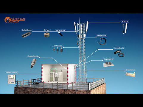
Telecom Base Station Materials: A 3D Walkthrough
 0:53:47
Analog Beamforming—What is it and How Does it Impact Phased-Array Radar and 5G?
 0:37:39
Ep 8. Analog versus Digital Beamforming (with Bengt Lindoff) [Wireless Future Podcast]
 1:46:47
Phased Array Beamforming: Understanding and Prototyping
 0:01:15
Logitech Rally: Crystal-Clear, Modular Audio for Video Meetings
 0:11:08
What is Massive MIMO?
 0:03:35
UniFi Expert's Corner: WiFi Performance
Комментарии