filmov
tv
Linear Power Supply Circuit [LM317, LM337, Adjustable & Low Noise]
Показать описание
Linear Power Supply Circuit [LM317, LM337, Adjustable & Low Noise]
A single-output transformer
=============================================
=============================================
=============================================
=============================================
Features:
AC – DC Conversion
Double output voltages (Positive – Ground – Negative)
Adjustable positive and negative rails
Just a Single-Output AC transformer
Output noise (20MHz-BWL, no load): Around 1.12mVpp
Low noise and stable outputs (ideal to power Opamps)
Output Voltage: +/-1.25V to +/-25V
Maximum output current: 300mA to 500mA
Cheap and easy to solder (all component packages are DIP)
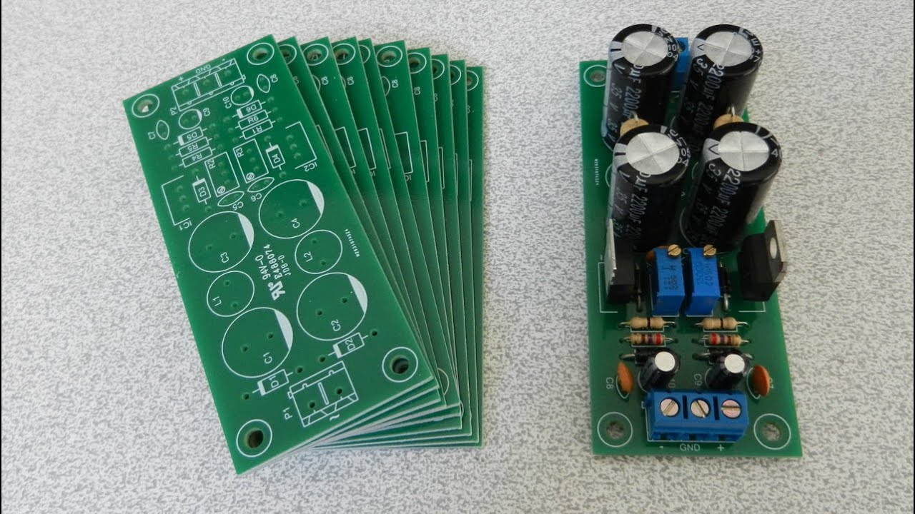
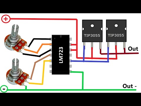
A double output low noise power supply is an essential tool for any electronics enthusiast. There are many circumstances that a double-output power supply is necessary such as designing pre-amplifiers and powering OPAMPs. In this article, we are going to build a linear power supply that a user can adjust its positive and negative rails independently. Moreover, just an ordinary single-output AC transformer is used at the input.D1 and D2 are rectifier diodes.
C1 and C2 build the first noise reduction filter stage. R1, R2, C1, C2, C3, C4, C5, and C6 build a low pass RC filter which reduces noise from both positive and negative rails. The behavior of this filter can be examined both in theory and practice. An oscilloscope with a bode plot feature can perform these measurements, such as a Siglent SDS1104X-E.IC1 [1] and IC2 [2] are the main regulation components of this circuit. According to the IC1 (LM317) datasheet: “The LM317 device is an adjustable three-terminal positive-voltage regulator capable of supplying more than 1.5 A over an output-voltage range of 1.25 V to 37 V. It requires only two external resistors to set the output voltage. The device features a typical line regulation of 0.01% and a typical load regulation of 0.1%. It includes current limiting, thermal overload protection, and safe operating area protection. Overload protection remains functional even if the ADJUST terminal is disconnected”.As it is clear, this regulator introduces good line and load regulation figures, therefore we can expect to get a stable output rail. This is identical to the IC2 (LM337). The only difference is that this chip is used to regulate the negative voltages.D3 and D4 are used for protection. The diodes provide a low-impedance discharge path to prevent the capacitors (C9 and C10) from discharging into the output of the regulators.R4 and R5 are used to adjust the output voltages. C7, C8, C9, and C10 are used to filter the remained output noises.
#adjustable_power_supply
#LM317
#LM337
A single-output transformer
=============================================
=============================================
=============================================
=============================================
Features:
AC – DC Conversion
Double output voltages (Positive – Ground – Negative)
Adjustable positive and negative rails
Just a Single-Output AC transformer
Output noise (20MHz-BWL, no load): Around 1.12mVpp
Low noise and stable outputs (ideal to power Opamps)
Output Voltage: +/-1.25V to +/-25V
Maximum output current: 300mA to 500mA
Cheap and easy to solder (all component packages are DIP)
A double output low noise power supply is an essential tool for any electronics enthusiast. There are many circumstances that a double-output power supply is necessary such as designing pre-amplifiers and powering OPAMPs. In this article, we are going to build a linear power supply that a user can adjust its positive and negative rails independently. Moreover, just an ordinary single-output AC transformer is used at the input.D1 and D2 are rectifier diodes.
C1 and C2 build the first noise reduction filter stage. R1, R2, C1, C2, C3, C4, C5, and C6 build a low pass RC filter which reduces noise from both positive and negative rails. The behavior of this filter can be examined both in theory and practice. An oscilloscope with a bode plot feature can perform these measurements, such as a Siglent SDS1104X-E.IC1 [1] and IC2 [2] are the main regulation components of this circuit. According to the IC1 (LM317) datasheet: “The LM317 device is an adjustable three-terminal positive-voltage regulator capable of supplying more than 1.5 A over an output-voltage range of 1.25 V to 37 V. It requires only two external resistors to set the output voltage. The device features a typical line regulation of 0.01% and a typical load regulation of 0.1%. It includes current limiting, thermal overload protection, and safe operating area protection. Overload protection remains functional even if the ADJUST terminal is disconnected”.As it is clear, this regulator introduces good line and load regulation figures, therefore we can expect to get a stable output rail. This is identical to the IC2 (LM337). The only difference is that this chip is used to regulate the negative voltages.D3 and D4 are used for protection. The diodes provide a low-impedance discharge path to prevent the capacitors (C9 and C10) from discharging into the output of the regulators.R4 and R5 are used to adjust the output voltages. C7, C8, C9, and C10 are used to filter the remained output noises.
#adjustable_power_supply
#LM317
#LM337
 0:07:59
Linear Power Supply Circuit [LM317, LM337, Adjustable & Low Noise]
 1:12:39
Linear DC Power Supplies - Designing & Building Custom DC Power Supplies
 0:06:26
0-30v 0-10A variable power supply Adjustable voltage and current
 0:06:39
How to make LM317 variable DC Power Supply with circuit diagram
 0:08:03
0-30v 0-10A Variable Power Supply Adjustable Voltage and Current / Constant Current and Voltage Mode
 0:04:08
LM317 Adjustable Voltage Regulator Tutorial
 0:10:36
Adjustable Voltage regulator LM317 how to make!
 0:11:34
DC Voltage and amp Adjustable power Supply, Simple DC voltage regulator
 0:17:44
LM317 Linear Voltage Regulator Kit: How Fast Can We Build It?
 0:04:20
IGBT Adjustable Power Supply 0-60V 30A | DC Voltage Regulator
 0:06:50
How to make Adjustable voltage DC Power Supply circuit using LM317 IC
 0:12:05
Building a Linear Power Supply, Part 5 Current Limiting
 0:05:46
voltage regulator lm317 power supply
 0:08:39
GADGETS#91 - LINEAR POWER SUPPLY add-on MODULE
 0:10:43
#548 LM317 with Transistor for more Current
 0:06:26
Current Boost LM317 Adj. Power Supply
 0:03:27
Voltage Regulator Circuit | LM317 Voltage Regulator Circuit
 0:37:41
EEVblog #221 - Lab Power Supply Design - Part 1
 0:06:00
Building a DIY LM317 Adjustable Power Supply
 0:06:23
High powerful voltage and current Adjustable power supply, Voltage and Current Adjustable
 0:29:36
Banggood LM317 regulated power supply build
 0:09:56
Simple Adjustable DC voltage power supply, Voltage regulator DIY
 0:00:35
LM317 Three-Pin Adjustable Regulator #electroniccomponents #semiconductor #lm317
 0:36:38
Building a Simple Linear Power Supply with an LM317 Linear Regulator
Комментарии