filmov
tv
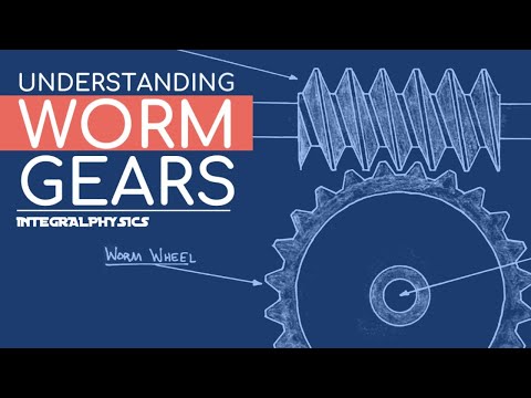
Worm Gears Explained, Calculated & Modeled

Показать описание
In this video we first hand draw a basic worm gear meshed with a worm wheel. Then we take a look at the function of a worm gear assembly and how to find the gear ratio of a worm gear assembly. Then we take a look at a 3d rendering a worm gear and worm wheel animated in Autodesk Inventor.
The subject of Worm Gears often come up in both high school and college physics and engineering classes. They are found in Project Lead the Way (PLTW), Principles of Engineering (POE), and AP Physics.
The subject of Worm Gears often come up in both high school and college physics and engineering classes. They are found in Project Lead the Way (PLTW), Principles of Engineering (POE), and AP Physics.
 0:07:32
Worm Gears Explained, Calculated & Modeled
 0:03:12
This is why worm gears are so cool...
 0:14:36
WORM GEARS - Forces and Speed Relations in Just Under 15 Minutes!
 0:02:11
Worm Gear Calculation || Reverse Engineering
 0:00:25
Worm gear 40:1
 0:03:25
How to calculate gear ratio for worm gear
 0:04:23
Worm Gear | Worm Gear Calculation | Different Calculations of Worm Gear |
 0:50:41
Worm Gear Center Distance and Efficiency
 0:20:49
Strength and Wear ratings of worm gears
 0:11:36
worm wheel Design calculation important formulas
 0:26:32
Analysis of Worm Gear (Numerical)
 0:00:19
Worm Gear Animation
 0:09:02
Worm gear Design Step by Step Procedure (How to calculate module)
 0:01:05
Gear 'Module' Explained in 1 Minute
 0:16:52
Design of worm gears
 0:01:09
Worm Gear Reducer Study : Use MS Excel to Calculate Dimensions of Worm & Worm wheel. KHK Worm Ge...
 0:05:09
Single Start,Double Start And Triple start worm gear | Types of Worm gear
 0:00:16
worm gear #maintenances #mechanical_device #gear
 0:00:23
🔴 Worm Gear WORKING 3D Animation ⚙️#shorts
 0:08:13
How to determine the Pitch or Module of a Gear
 0:04:13
How Do You Calculate a Worm Gear Ratio?
 0:05:42
Worm Gear Calculation and Design (MITCalc-12)
 0:11:30
Force Analysis of Worm Gears
 0:18:37
How to model Worm Gears (Gears pt 7/?)
Комментарии