filmov
tv
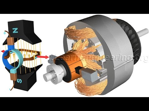
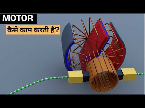
DC Motor, How it works?

Показать описание
The working of a DC motor is well explained in this video with the help of animation. Construction details of DC Motor, Shunt & Series motor, concept of back EMF are also explained in this video.
 0:04:50
DC Motor, How it works?
 0:10:03
How does an Electric Motor work? (DC Motor)
 0:04:50
How does an Electric Motor work? (DC Motor)
 0:05:36
Working Principle of DC Motor (animation of elementary model)
 0:15:32
How does an Electric Motor work? DC Motor explained
 0:05:03
GCSE Physics - How the Electric Motor Works #80
 0:13:45
How Motors Work For Beginners (Episode 1): The DC Motor: 032
 0:04:40
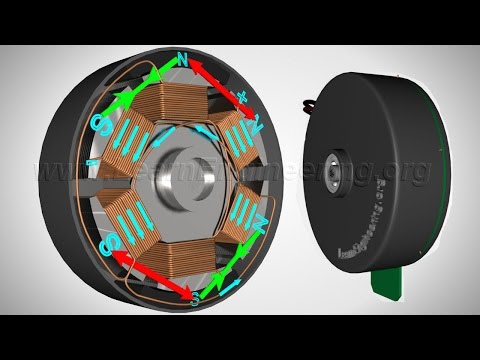
Brushless DC Motor, How it works ?
 0:02:13
Amazing Motor // Power Of Motor free 500 volt // @Technicalsourav507
 0:05:31
How DC Motors Work
 0:10:03
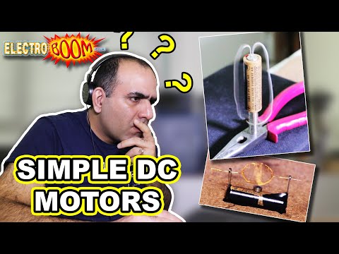
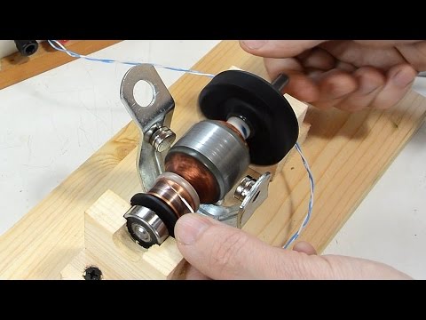
Super Simple DC Motor
 0:07:23
How DC motors and universal motors work
 0:03:09
AC Motor Vs DC Motor | Key Difference between DC and AC Motors
 0:04:32
DC Motor - 3 Coil, How it works ?
 0:10:35
Working principle of dc motor with animation | How does electric-dc motor works? | Mruduraj
 0:06:49
How does an Electric Motor Work? The fundamental concept of Motor | electric Motor
 0:03:35
How DC motors work - Electromagnetic Field and 3D animation
 0:02:28
Electric Motor
 0:16:12
Brushless Motor - How they work BLDC ESC PWM
 0:07:40
How Electric Motor Work - 3D Animation
 0:01:27
How a Brushless DC Motor Works
 0:06:59
Working Principle of DC Generator | [Electric Machine #1]
 0:00:42
Brushless DC motor animation
 0:11:44
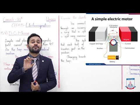
Class 10 - Physics - Chapter 15 - Lecture 4 - 15.4 D.C. Motor - Allied Schools
Комментарии