filmov
tv
Mechanical Engineering: Trusses, Bridges & Other Structures (16 of 34) Pratt Bridge: Example 1

Показать описание
In this video I will find the compression/tension and magnitude of each member, and the forces at each support of a pratt bridge problem.
Next video in this series can be seen at:
 0:14:56
Mechanical Engineering: Trusses, Bridges & Other Structures (16 of 34) Pratt Bridge: Example 1
 0:17:41
Understanding and Analysing Trusses
 0:04:24
Mechanical Engineering: Trusses, Bridges & Other Structures (29 of 34) Tension vs Compression 3
 0:02:53
Mechanical Engineering: Trusses, Bridges & Other Structures (3 of 34) Ex. of Bridge Trusses: 1
 0:11:18
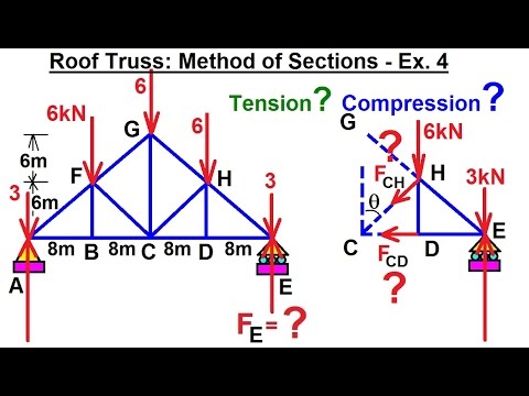
Mechanical Engineering: Trusses, Bridges & Other Structures (21 of 34) Roof Truss: Sections: Ex ...
 0:09:40
The Secret to the Truss Strength!
 0:12:52
Mechanical Engineering: Trusses, Bridges & Other Structures (10 of 34) Truss: Ex. 1
 0:06:35
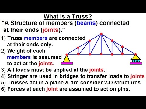
Mechanical Engineering: Trusses, Bridges & Other Structures (1 of 34) What is a Truss?
 0:04:20
Mechanical Engineering: Trusses, Bridges & Other Structures (6 of 34) What are Tension & Com...
 0:05:36
Mechanical Engineering: Trusses, Bridges & Other Structures (9 of 34) What are Internal Forces?
 0:01:52
Mechanical Engineering: Trusses, Bridges & Other Structures (4 of 34) Ex. of Bridge Trusses: 2
 0:06:47
Mechanical Engineering: Trusses, Bridges & Other Structures (18 of 34) Pratt Bridge: Sections: E...
 0:06:03
Mechanical Engineering: Trusses, Bridges & Other Structures (27 of 34) Tension vs Compression 1
 0:14:50
Mechanical Engineering: Trusses, Bridges & Other Structures (34 of 34) Forces=? on Members (Sect...
 0:11:08
Mechanical Engineering: Trusses, Bridges & Other Structures (14 of 34) Truss: Ex. 4
 0:06:30
Mechanical Engineering: Trusses, Bridges & Other Structures (20 of 34) Pratt Bridge: Sections: E...
 0:09:04
Mechanical Engineering: Trusses, Bridges & Other Structures (15 of 34) Truss: Ex. 5
 0:17:20
Mechanical Engineering: Trusses, Bridges & Other Structures (32 of 34) Forces=? on Members 3
 0:03:13
Mechanical Engineering: Trusses, Bridges & Other Structures (2 of 34) Ex. of Roof Trusses
 0:10:58
Trusses Method of Joints | Mechanics Statics | Learn to Solve Questions
 0:04:26
Understanding Trusses
 0:05:35
Mechanical Engineering: Trusses, Bridges & Other Structures (23 of 34) Sum of Forces Technique
 0:11:58
Truss Bridge | Types of Truss Bridges | Analysis of Trusses | Method of Joints | Bridge Engineering
 0:04:03
Mechanical Engineering: Trusses, Bridges & Other Structures (7 of 34) What are Joints & Memb...
Комментарии