filmov
tv
The Secret to the Truss Strength!

Показать описание
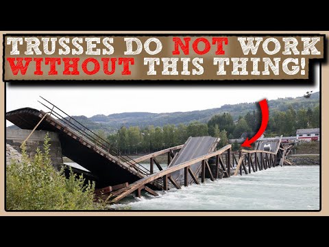
Truss structures are more common than you think. But why do we use them? Beams seem to work fine right, well yes but there is a catch! The trusses are mostly used in bridges, roofs of venues, some cars and many other places. But how do they work and what is their advantage over beams? In this video, we dive deeper on truss structures and the secret to their efficiency. The video is supplemented by a scaled experiment that practically shows the advantages of the truss.
This video was sponsored by Brilliant
References:
[1] M. Carver, "Tennessee’s Survey Report for Historic Highway Bridges," Ambrose Printing Company, Nashville, Tennessee , 2008.
[2] J. M. Gere and B. J. Goodno, Mechanics of Materials, Cengage Learning, 2013.
[3] R. C. Hibbeler, Structural Analysis, Upper Saddle River, New Jersey: Pearson Prentice Hall, 2015.
 0:09:40
The Secret to the Truss Strength!
 0:17:41
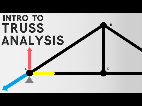
Understanding and Analysing Trusses
 0:08:47
Use the Method of Joints and BASIC Physics to Analyze a Truss | Statics
 0:01:00
IS A TRUSS STRONGER THAN A BEAM??
 0:00:52
Bridge of 4g sustained 5000g weight. Bridge with 1000% efficiency. #truss #bridge #design #india
 0:18:10
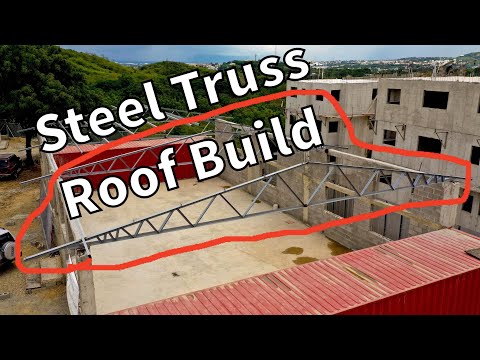
Building & Installing 40' Steel Roof Trusses
 0:11:34
Make Truss Design EASY + Civil PE Exam Review Problem
 0:00:54
Truss Bridge Explained
 0:06:46
Understanding the Steel frame construction roof truss | Steel construction | 3D animation
 0:00:21
Long Span Light Weight Metal Steel Structures Roof Truss Shed Design For warehouse
 0:00:16
TRUSS BRIDGE #shorts #civilengineering #structural#truss #structuredesign
 0:08:18
Engineering Statics | Theory | Truss Zero Force Members
 0:00:13
Roof steel trusses#steel #building #cnc #truss
 0:01:52
‘Appalling’: Liz Truss slams the Secret Service’s ‘major failings’ in protecting Trump
 0:06:19
TRUSS :: METHOD OF JOINTS IN 6 MINUTES
 0:10:17
Secret; Making Truss cottage Vlog | MrMin
 0:00:20
Brilliant truss design! #framing #construction
 0:00:09
Wr secret twisty truss obby #gaming #roblox #obby #speedrun #shorts
 0:00:10
Got the bounce- time records #spedrun #obby #bounce #truss
 0:00:31
setting truss an gluelam beams
 0:00:11
⚡️Fast Secret Twisty Truss NB Speedrun ⚡️#shorts #noahstimetrialx #roblox #speedrun #fyp #viral #YA...
 0:00:57
how to build a I beam truss for metal buildings
 0:21:04
DESIGN OF STEEL TRUSS | PART A
 0:00:14
Truss roof construction #carpentry #joinery #builders #team #love #work
Комментарии