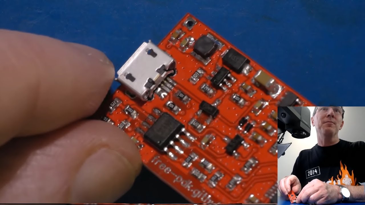
EEVblog #1306 (2 of 5): PCB SMD Hand Soldering & Assembly

preview_player
Показать описание
Part two in a five part video series on building the Free PDK open source programmer for the 3 Cent Padauk microcontrollers.
A new video released 9am Sydney time every day.
Part 2 is inspecting and assembling the PCB, with lots of tips on surface mount PCB soldering and assembly.

#Padauk #PCB #Assembly

Support the EEVblog through Patreon!

Buy anything through that link and Dave gets a commission at no cost to you.

Donate With Bitcoin & Other Crypto Currencies!

Рекомендации по теме
Комментарии
Автор

That drag soldering looked far too easy, clean and straight forward. Where's the five minutes of cross-eyed swearing and trying to use solder braid to tidy things up? ;)

ncot_tech
Автор

You can actually solder SMD resistors and caps on their side. I did this at work once to see if the guy inspecting the boards was doing a good job!

userPrehistoricman
Автор

What a mad man puts also value on the silkscreen, I often struggle to get enough space for idents.
Now working on a PCB that I so dense that I will very likely need to remove idents as well...

Arek_R.
Автор

Oh man, I am glad that I am going down the solder paste and stencil path for this. No way I would want to spend that amount of effort for that all, $7 is cheap for a lot of time fiddling

IAmPattycakes
Автор

The upside down SMD resistors actually do have a benefit in high frequency applications where you can see reduced parasitic effects, you can even buy them sometimes with the components upside down in the reel already!

rjordans
Автор

Louis Rossmann- You didn't use enough flux, Dave!

I was taught SMD hand rework by our test/rework lead, and he learned it working the lines at a high end manufacturer in Vietnam, where doing pre-prod prototypes and production line rework, and although Louis goes a bit overboard, seriously, using a fair bit of flux makes hand soldering SMD components so much easier and neater. You do have to flush the board to clean off the excess flux afterwards (and you have to do this anyways), but it's an easy trade-off for the time saved in soldering and the neat, virtually perfect joints without dags.. I also get a fine tip Sharpie marker and dot in between the pads before each component type/value so I can go full speed and tack on all of the same components in one go vs having to refer back to the docs between each component (ie dot each cap, solder the caps over the dots, then repeat for each value and each component). This is a good practice even if you have component numbers listed unless you also do component values as well because it lets you just visually pick and place very quickly..

FlyingDismount
Автор

My tutor for smd assembly in 1997 was fond of saying "flux is your friend". I would have done much as Dave did here - pretinning one pad of each part, but then I'd wipe the entire board with a flux pen, or smear paste flux with a fingertip if using Louis Rossmann's favorite flux. I prefer to use Kester's line of 331 cored solder & its companion flux - the water-soluble flux & its residue is conductive, and must be washed in warm [not hot] water to rinse it all off, but the final board is clean and shiny, ready for an eventual spray with conformal coat to protect it against later damage by moisture and/or dust/dirt. Each to his own...

jrb_sland
Автор

Louis Rossmann would say "That is not nearly enough flux!"

wburger
Автор

Dave, I reckon that this is your best tutorial yet. I love the multi-part, 'warts and all' approach and have just ordered some PCBs and components to try this myself. I expect that with my poor eyesight, I'll see a few solder bridges - still, the parts are incredibly cheap, even with shipping - I'm prepared to make mistakes. As you said, mistakes are part of the fun. Great stuff.

brooknet
Автор

You made your point well enough by addressing the lack of labels on the solder mask, but quite honestly if it was me, I would have sent it back to them and said won't use without labels. Your time and my time are worth something too, and having to do forensic work just to assemble one PCB is ridiculous. Nevertheless, I have been in this situation too, and my best backup is either print out the schematic and check off with pen, or do a quick-and-dirty Photoshop overlay of the schematic and a picture of the board.

chrispletcher
Автор

Soldering resistors upside down is done intentionally on RF boards for lower inductance. The black part of the resistor is the actual resistive metal film-- the white part is just a ceramic dielectric carrier.

Ziferten
Автор

I really appreciate seeing Dave struggle. Knowing he's not gotten all the parts, which he thought he had, some how assures me. All of us Noobs, assessing only how to solder SMT parts - seeing the frustration of manual assembly. More flux would likely have helped wick some of the through holes.etc.. Thank you DAVE! Really, ! We see the human condition, against dealing with parts meant for robotic assembly. Quite telling. I enjoyed this. It is assuring. REALITY TECH TV- /-you tube.

WrankledEngine
Автор

SMD LEDs should have green triangle on the other side, on the schematic you can see it @17:14 the tip of the triangle goes to the chamfered edge

Автор

Great series of videos .
So much information for newbies like me.
Thank you 😁

eebaker
Автор

Like Macca's.... I'M LOVIN IT ❤

"Must See TV" is back, baby!

ovalwingnut
Автор

@4:30 yep I always put on the value and ID on the boards I make, makes it dead easy to hand assemble them and fault find later. although if I had to cram everything into a small space I would have to go without them.

TheDefpom
Автор

If you aren't going to clean the PCB with something like a vapor tank (which few do-it-at-home types have), then I highly recommend going over that TQFP with a hot air gun until the solder melts. All fluxes are corrosive; no-clean types need to raised to activation temperature before the corrosive elements are rendered inert (encapsulated or otherwise deactivated).

Once you've made the decision to apply flux to the board (as was done here with the pen), any flux finding its way underneath the IC is still active. Using a toothbrush and running water to clean the board will not remove the flux trapped underneath the IC. The unactivated flux will happily attack any exposed copper underneath the IC (especially vias, which tend to not be plugged by the mask), and the board will die months to years later (depending on how active the flux is).

Normally you wouldn't want to expose the board to any additional temperature cycling after the initial solder job, but this is one time where the risk of damage due to the additional thermal stress is much more palatable than the near-certainty of the board being rendered useless in the future.

glenndoiron
Автор

I've done countless SMT assemblies many with 300+ parts on them which seems daunting unless you have a good process. To speed things up, i would start by taking the parts placement drawing, and the Bill Of Material and color the location on the drawing with a colored highlighter as well as color that component line on the BOM. If the BOM line item has a dozen capacitors with the same value, you had a dozen highlighted components with the same color. It did take a few copies of the placement drawing since there are just so many colors of highlighter pens. I would mark on the drawing the line item numbers from the BOM on each page. Once finished I could find the parts location very quickly. It saved hours just looking for where the parts are when hand soldering. It was interesting to see you used the same technique of applying solder to one pad, placing the part with tweezers and reflowing the solder. I found it best to solder one pad on all the components before placing any parts to avoid interference from installed parts. BTW, my soldering iron of choice is Metcal.

mrbill
Автор

I use cross tweezers for SMD soldering. With this you can clamp the fleas wonderfully and you don't get a cramp in your fingers ;-)

Soundfactory
Автор

As always a very informative video, thx Dave👍

automated