filmov
tv
FM Receiver Radio Build DIY

Показать описание
This FM transistor receiver is an improved designed from a commonly found circuit. The video includes the schematic and a demonstration. Enjoy!
 0:06:58
FM Receiver Radio Build DIY
 0:05:31
Build your own Crude FM Radio || FM,AM Tutorial
 0:00:15
Simple FM Transmitter Circuit diagram
 0:09:19
FM Radio Receiver DIY - 87/108 MHz (Part-1 PCB Assembly)
 0:04:57
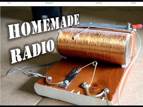
Homemade Radio
 0:08:26
FM Receiver Radio Build DIY - Part 2
 0:12:06
DIY AM/FM Radio Kit: Crafting Radio Receiver
 0:00:52
Mini FM Receiver With BC547 No Coil using
 0:04:19
Single transistor FM receiver circuit. Easy to build, works great!
 0:03:00
How to make FM Radio receiver at home
 0:00:11
DIY AM Crystal Radio Set with small Amplifier
 0:05:01
7Kms Long Range FM Transmitter || Pirate Radio Station
 0:30:24
Build AM FM Radio Receiver DIY kit CF210SP
 0:00:19
DIY 1KM FM Transmitter Circuit Diagram #khairunelectronicsbd #shorts #diycircuit
 0:00:38
FM Radio Hack (Dirt Cheap)
 0:00:25
FM antenna||#shorts ||
 0:00:13
fm transmitter long range
 0:01:38
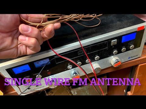
How to improve FM signal On radio with a single wire antenna Poor signal Reception static
 0:11:23
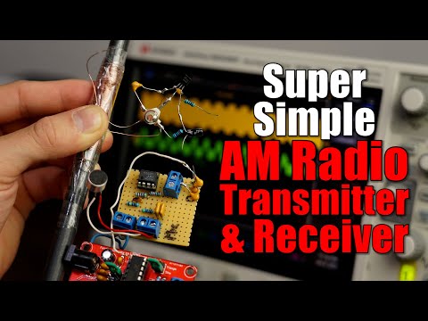
Building a Super Simple AM Radio Transmitter & Receiver! Keeping Wireless Audio Communication ea...
 0:15:40
easy kit build: fm radio receiver
 0:07:36
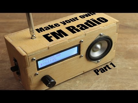
Make your own FM Radio - Part 1
 0:00:06
We Built a Simple FM Transmitter Circuit
 0:00:36
How to Make a Radio Receiver from Foil #physics #coherer
 0:00:13
FM radio transmitter circuit #shorts
Комментарии