filmov
tv
Flatness Tolerance - How to apply and measure

Показать описание
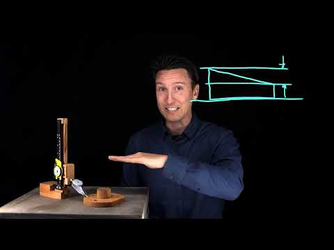
This video shows everything you need to know about flatness tolerance in ASME Y14.5. It includes proper applications and functional uses. It also has demonstrations on how to inspect. Per unit area flatness is also covered.
GeoTol Inc. is a full-service training and consulting firm on geometric dimensioning and tolerancing. Please visit our website for information regarding onsite training, online training, virtual training, consulting, books, pocket guides, DVD video, leader PowerPoint and model set packages.
#profile tolerance #datum #datum feature #asme #asme Y14.5 #Y14.5
#GD&T #geometric tolerance #Y14.5-2018
 0:10:07
Flatness Tolerance - How to apply and measure
 0:02:48
Flatness Tolerance
 0:17:07
GD&T Basics - Flatness Lesson
 0:22:24
Lesson Flatness Tolerance
 0:15:10
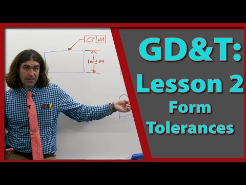
GD&T Lesson 2: Form Tolerances
 0:04:41
GD&T Tutorial 21 : Flatness Tolerance
 0:04:47
Unit Area Flatness
 0:02:08
Flatness and Straightness
 0:05:32
Flatness on a Per Unit Basis
 0:10:22
GD&T; flatness
 0:21:16
Tutorial - 20 GD&T ||Flatness Tolerance||
 0:09:13
How to give Flatness tolerance in drawing.
 0:06:59
Aluminum Extrusion Tolerances - Flatness
 0:01:41
GD&T : How Flatness saves money compared to traditional tolerancing
 0:03:11
Flatness Applied to Derived Median Plane
 0:07:03
GD&T: Profile vs Flatness
 0:04:16
flatness and position tolerance
 0:03:56
Flatness: GD&T Explained Like You Are 5!
 0:02:24
04 GD&T Flatness
 0:06:03
Surface Finish and Flatness
 0:03:06
FLATNESS TOLS
 0:29:32
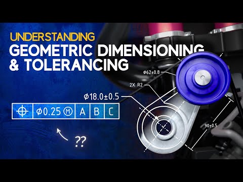
Understanding GD&T
 0:01:32
Flatness tolerance applied to a surface is unilateral
 0:08:30
GD&T Inspection: Flatness, Parallelism and Profile
Комментарии