filmov
tv
Variable Frequency Drives Explained | VFD Basics - Part 2

Показать описание
▶ You can read the full post here
⌚Timestamps
00:00 - Intro
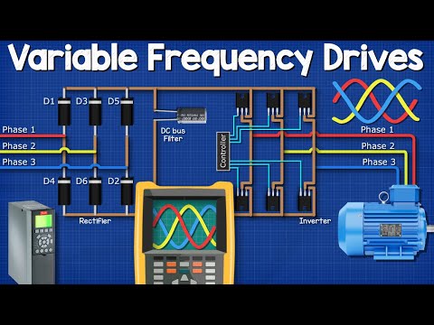
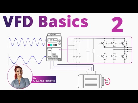
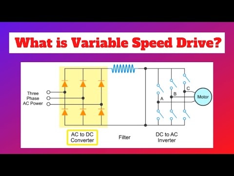
01:00 - VFD diagram
01:54 - How does an IGBT work?
03:58 - IGBT module in VFD
=============================
Welcome to Part 2 of Variable Frequency Drives Explained!
As we have learned in the previous lesson, there are many applications where in order to meet varying demands, motors need to throttle down output.
Additionally, constantly running a motor at its full speed can be costly.
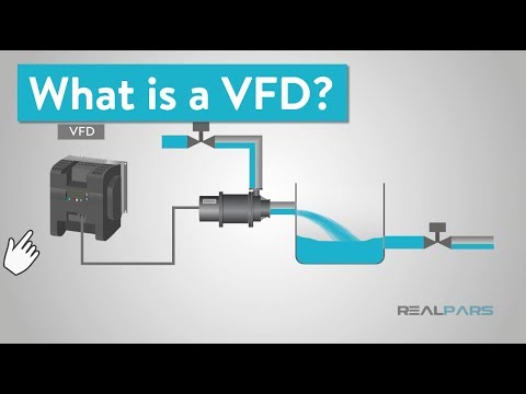
A variable frequency drive is a type of controller that has the function of driving an electric motor by varying the frequency and voltage that is supplied to control its speed and power.
VFDs are widely used in both industrial and commercial applications, such as control of fans, pumps, compressors, HVACs, and even roller coasters!
It is impossible to talk about VFDs and Insulated Gate Bipolar Transistors, also known as IGBTs without understanding what Pulse Width Modulation (PWM) is.
An analog input signal can be modulated by generating variable width pulses to represent its amplitude. In a very brief summary, PWM is a way to control analog signals with a digital output.
To understand the IGBT’s function in a VFD, it is important to understand how an IGBT works singularly.
At the simplest level, an insulated gate bipolar transistor (IGBT) is a switch used to allow power to flow when it is turned on and to stop when it is turned off.
It is important to note, however, that they have the capability of switching on and off several thousand times every second!
An IGBT is a solid-state device, which means it has no moving parts.
Rather than opening and closing a physical connection, it is operated by applying a voltage to a semiconductor component, called a gate, that changes its properties to create or block an electrical path.
IGBT terminals (pins) represent the Gate, the Collector, and the Emitter.
Current flows along the conductance path composed by the Collector and the Emitter, while the Gate controls the device.
Now that we have an understanding of how our IGBTs work, let’s go back to the application of IGBTs in VFDs, and let’s represent our IGBTs as contact switches for a simpler understanding.
The top IGBTs are in the positive DC bus, and the lowers are in the negative DC bus, so when one of the top switches is closed, that motor phase and voltage then become positive.
On the other hand, when one of the lower switches is closed, that motor phase and voltage then become negative.
Therefore, by controlling the speed and sequence that those switches open and close, we can control the phases and frequency of our signal: zero, negative, or positive.
It is important to note that VFDs output signal is a PWM signal, which turns out to be a rectangular waveform.
This wave is crucial in the operation of a VFD, as it is this variable voltage and frequency that will enable the VFD to control the motor’s speed.
VFDs output signal is a PWM signal, which turns out to be a rectangular waveform. This wave is crucial in the operation of a VFD.
The control processor of a VFD contains a program that is not typically user-accessible, however, there are many parameters and settings that can be adjusted and tuned for optimal VFD operation for each application where it’s been used to meet specific motor and driven equipment specifications and needs.
The following are common adjustable parameters and settings in a VFD:
- Tunable: Proportional, Integral, Derivative (PID)
- Minimum and Maximum Speed
- Current Limit
The number of parameters varies based on the level of complexity of the VFD. They can range from 50 to over 200 parameters!
=============================
=============================
Missed our most recent videos? Watch them here:
=============================
To stay up to date with our last videos, make sure to subscribe to this YouTube channel:
=============================
=============================
#RealPars #VFD #IGBT
 0:15:18
Variable Frequency Drives Explained - VFD Basics IGBT inverter
 0:08:35
Variable Frequency Drives Explained | VFD Basics - Part 1
 0:05:20
What is a VFD? (Variable Frequency Drive)
 0:08:20
Variable Frequency Drives Explained | VFD Basics - Part 2
 0:15:52
VFD 101 Basics
 0:02:56
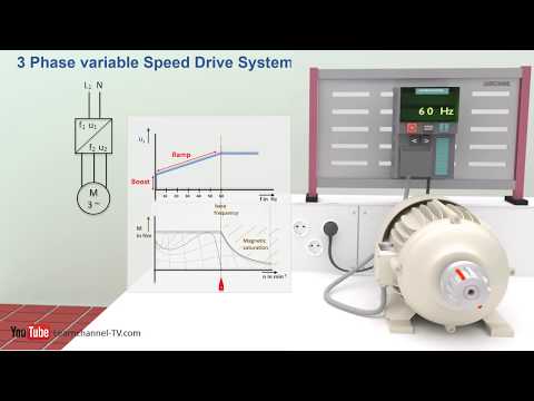
What is Variable Speed Drive? | Basics and Working Principle
 0:03:28
How a VFD or variable frequency drive works - Technical animation
 0:04:11
Variable Frequency Drives | What is VFD
 0:13:38
How Variable Frequency Drives Work in HVAC Systems
 0:00:28
Motor Forward / Reverse with Variable Frequency Drive VFD@CNCElectric1988
 0:03:10
What is a variable speed drive?
 0:06:58
What Types of Motors Can Be Used with VFDs?
 0:05:39
How Variable Frequency Drive (VFD) controls Motor Speed? - Inverter Basics Explained.
 0:00:39
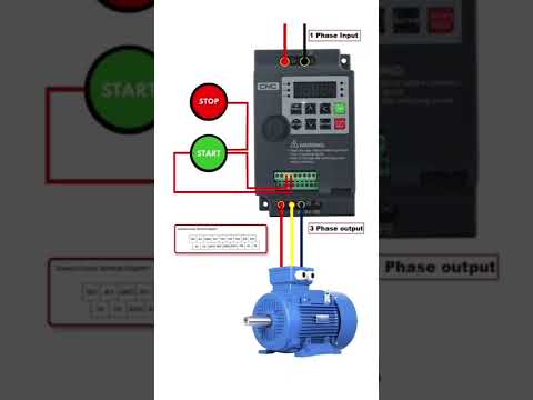
Three wire controlling of variable frequency drive VFD
 0:25:33
Drive Basics
 0:07:15
VFD 3 Wire Control Wiring with Push Button and VFD Programming @TheElectricalGuy
 0:07:30
What is the Difference between VFD and Soft Starter?
 0:05:27
Why We Use Variable Frequency Drive | Variable Frequency Drive explained
 0:05:02
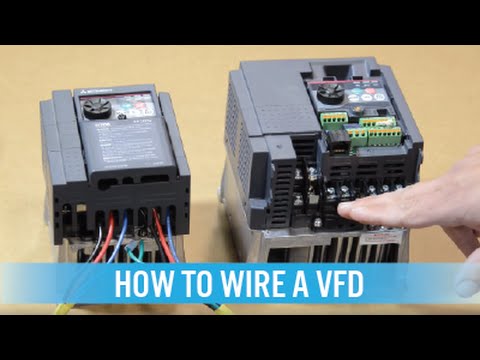
How to wire a VFD / variable frequency drive
 0:06:12
Interview Question On VFD| What is Variable Frequency Drive | Variable Frequency Drive Working
 0:01:01
Variable Frequency Drives Explained & What is a VFD?
 0:12:13
Variable Frequency Drive (VFD), How it Works?
 0:00:19
What are VFD's? (Variable Frequency Drives)
 0:03:16
How to size and select a Variable Frequency Drive at Galco.com
Комментарии