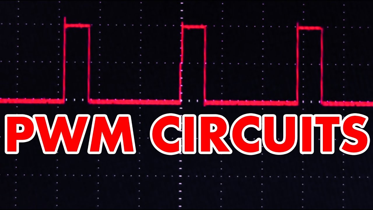
What is PWM? Pulse Width Modulation tutorial!

preview_player
Показать описание
I cover the basics of PWM and show you how to cheaply build a PWM circuit that can dim LEDs, control the speed of a motor, or control the power going to pretty much anything you want!
Рекомендации по теме
Комментарии
Автор

Interested in learning about wireless power? Subscribers can get up to 80% off my course Wireless Power to the People - Wireless Charging 101 on udemy using the coupon code "YOUTUBE"

Afrotechmods
Автор

You sir make the best electronics tutorials on the internet! Don't ever stop!

bizzlemedia
Автор

Very nice and clear presentation. Thank you very much. One good presentation is much more efficient for a beginner than reading 10 pages of silly text, and gives appetite for further helpful reading if needed.

fahmylina
Автор

Such simple straightforward explanation! So easy to brush up long forgotten knowledge! Thank you!!!

SohamSinha
Автор

@blacklust007 Excellent question. The LM317 is a linear voltage regulator which is inherently inefficient. It burns up excess voltage as heat to get the output voltage you want. Power loss will be (Vin - Vout) * Iout. PWM is switching between fully off and fully on, so it will be much more efficient and generate less heat.

Afrotechmods
Автор

Why can't all tutorials be like this? Expanding slightly on the circuit construction would be the only added benefit here I can see. Kudos +Afrotechmods

TravisCrowder
Автор

Trust me I have been reading about PWM. For quite a bit for now. Nothing is as perfect as this video. The content the narration just perfect.

aadarshshetty
Автор

@nonodalloo The main thing that will determine the current limit is the transistor you use. You should try find a low resistance N channel MOSFET, put a heatsink on it, and get a schottky diode rated for 5A to put in antiparallel with the motor.

Afrotechmods
Автор

When you noticed that this video was uploaded about 10 years ago 😂😂 but is more useful than the new ones around

frankcastle
Автор

I built a PWM circuit using your diagram to control current flowing through a non-inductive piece of nichrome wire. Works like a charm. I picked a TIP141 NPN Power Transistor. Before using the 555 I tested it with a function generator and discovered the optimal switching frequency for PWM was about 1khz (close to what you have). In the datasheet TIP141 lists switch on time as 0.9μs and switch off as 11μs. I figured that by adding the values I'd get a full cycle of 11.9μs and a bandwidth cap of 84Khz, yet when cranking up the function generator, I found the real bottleneck to be closer to 8Khz. Pass that TIP141 wasn't able to keep up.
Am I calculating the full cycle wrong is the discrepancy caused by the fact my test conditions (load and base-emitter voltage) being different from those in the TIP141 datasheet?

enilenis
Автор

@jwhill15 Sure. Use a separate power supply for the 555, (roughly 10V will do) and then 24V will go on the high side of the motor. Make sure the grounds are all connected.

Afrotechmods
Автор

I'm getting started on electronics and find this one of the best channels on the subject. Also good humor and excellent voice talent.

shahzadm
Автор

Thank you!!! The difference between using a voltage regulator or potentiometer and a pulse width modulator really cleared a lot of things.

Zarif
Автор

thank you, i have a new knowledge after 10 year you upload this video on youtube

ducbui
Автор

You set new standards in clear communications. Stunningly good video. Thank you friend.

tobyhallam
Автор

The PWM output goes though an inductor to a capacitor to filter the waveform into DC. Usually there is a Zener diode to clamp the voltage, but the efficiency is still really good at 80 - 90 percent. Look up the LT3505 chip for a typical example.

AltRage
Автор

Yup. There's also loads of prebuilt motor controller solutions out there. Just search for motor speed controller. Also, check out Robot Marketplace.

Afrotechmods
Автор

@spelunkerd If you energize a coil like in a motor, what happens is, you establish a magnetic field across it. When the power pulse goes away, the field collapses back across the windings, inducing a voltage back across the coil. Depending the value of that coil, it can be a fairly high voltage. That voltage can destroy your transistor or FET so the diode blocks such voltage and sends it back to the coil to be dissipated instead of across your transistor. This effect is called "back EMF".

Landotter
Автор

It's awesome. I heard PWM many time but after watching this video I know that fully.

Thanks a lot.

piyushpv
Автор

I tried this with a TLC555 and nope doesn't work! I kept trying and couldn't get it. So finally I ordered an NE555 and sure enough! it went from 0.2% to 99.9%! Lol, I guess you weren't kidding when you said it won't work will an TLC555. I'am gonna use this on my DIY electric go kart. Thanks Afrotechmods!

robertcreed