filmov
tv
Arduino Based Low Voltage Vacuum Tube Tester

Показать описание
In this episode we take a stab at building a vacuum tube tester that gives us some proper, usable data! Granted, it’s all at super low voltages, just 24V in this case, but that actually works out perfectly for the types of circuits that we commonly build. Most importantly though, this was all done for extremely cheap – in total, there is less then $30 worth of parts involved in the entire build!
Schematic, gerber and code files here:
If you want to support the channel please hop over to Patreon:
Also, we now have some epic shirts for sale!
Timelapse Music:
Artist: C7, Jamphibious
Title: Mega Man 3 "Shadow's Lounge"
Intro Music adapted from:
Artist: The Runaway Five
Title: The Shinra Shuffle
Come join us on Discord and Twitter!
Thanks for watching!
Chapters
0:00 Intro
2:47 Using the tester
4:08 Testing the “bad” tubes
6:43 Tester construction
9:33 Arduino code
12:32 Building the PCB
14:46 Testing the finished version
18:04 Outro
19:17 Bunny!
 0:19:34
Arduino Based Low Voltage Vacuum Tube Tester
 0:07:24
How to Make Arduino based Smart Vacuum Cleaner Robot Best for Science Project
 0:05:23
How To Make An Automatic Object Sensing Smart Dustbin - DIY Project
 0:00:16
Amazing arduino project | Check description to get free money.
 0:00:40
Arduino project 😎^ Arduino #arduino #2022 #2021 #2023 #dc #arduinoproject #diy #foryou
 0:00:14
Before safety was invented...
 0:01:14
diy amplifier with arduino switching inputs and vacuum fluorescent display
 0:08:29
Arduino All-in-One Robot
 0:00:17
Arduino - Driving DC Motor (Water Pump) with Relay
 0:00:43
final year diploma engineering project #viral #mechanical
 0:00:12
Lipo 4s under volt super explosion
 0:29:11
SAVING 2500 $ - DIY Arduino Vacuum Gauge Controller
 0:00:15
Turn Anything Into A Speaker😱 #travelhack
 0:00:45
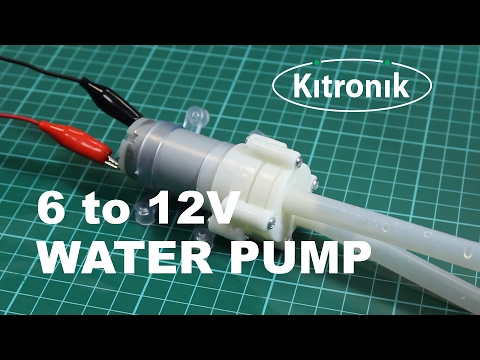
R385 diaphragm pump (6-12V) - Kitronik
 0:16:30
Using Vacuum Fluorescent Displays (VFDs) with an Arduino
 0:00:16
Lung inflation in Science Lesson #science #teacher #biology
 0:19:34
A Low Voltage Vacuum Tube OTL Audio Amplifier
 0:13:29
ARDUINO + VACUUM PUMP EXPLAINED #vacuumpump #arduino #esp32
 0:05:53
DIY How to Make Amazing Robot Vacuum Cleaner
 0:01:00
Arduino mechanical arm pump suction cup upgrade
 0:06:56
Homemade arduino controller for pirani vacuum gauge
 0:00:24
Become An Electrical Lineworker
 0:01:00
How they Make Electric MOTOR in Factory With Amazing Skills
 0:23:01
The Ultimate Floor Cleaning Robot (Version 2.0) | How To Make
Комментарии