filmov
tv
Single phase motor forward and reverse wiring

Показать описание
The structure of the 1-phase motor determines that the reverse rotation is generally completed by hardware. It is recommended to use a 3-phase motor + VFD.
A three-phase motor has three sets of coils. When it is connected to a three-phase AC power supply, it will generate a rotating magnetic field. The rotating magnetic field cuts the rotor windings and induces current on the rotor windings, and then the rotor is subjected to electromagnetic force in the magnetic field to rotate.
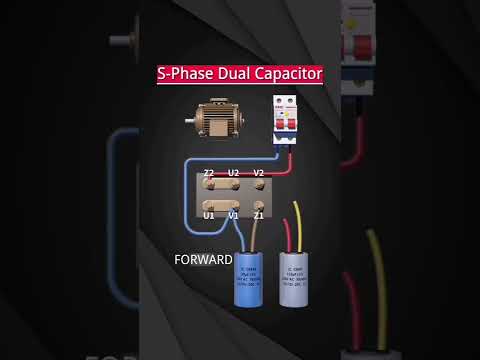
Single-phase motors are different from three-phase motors. Single-phase motors have only two coils, the main coil and the secondary coil. If the main coil and the auxiliary coil are supplied with single-phase electricity at the same time, the magnetic field generated by them and the force received by the rotor are the same and are in a static state. In order to rotate the magnetic field generated by the main and auxiliary coils, it is necessary to pass alternating currents with different phase sequences to the main and auxiliary coils.
But single-phase AC motors only have single-phase power, so how can we get two different phases of AC power simply and economically? At this time, a capacitor is needed to realize the phase shift, that is, a capacitor is connected in series with the power supply on the secondary coil.
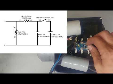
For industrial high-power single-phase motors, if only one capacitor is used to both start and run, its starting torque is small. In addition, the load it carries is relatively heavy, so it is easy to cause difficulty in starting. At this time, a large capacitor needs to be connected in parallel with the running capacitor to increase the starting torque. This capacitor is called "starting capacitor".
A three-phase motor has three sets of coils. When it is connected to a three-phase AC power supply, it will generate a rotating magnetic field. The rotating magnetic field cuts the rotor windings and induces current on the rotor windings, and then the rotor is subjected to electromagnetic force in the magnetic field to rotate.
Single-phase motors are different from three-phase motors. Single-phase motors have only two coils, the main coil and the secondary coil. If the main coil and the auxiliary coil are supplied with single-phase electricity at the same time, the magnetic field generated by them and the force received by the rotor are the same and are in a static state. In order to rotate the magnetic field generated by the main and auxiliary coils, it is necessary to pass alternating currents with different phase sequences to the main and auxiliary coils.
But single-phase AC motors only have single-phase power, so how can we get two different phases of AC power simply and economically? At this time, a capacitor is needed to realize the phase shift, that is, a capacitor is connected in series with the power supply on the secondary coil.
For industrial high-power single-phase motors, if only one capacitor is used to both start and run, its starting torque is small. In addition, the load it carries is relatively heavy, so it is easy to cause difficulty in starting. At this time, a large capacitor needs to be connected in parallel with the running capacitor to increase the starting torque. This capacitor is called "starting capacitor".
 0:03:14
How to Run Single Phase Motor Forward and Reverse | Single Phase Motor Forward Reverse
 0:02:46
Motor Reverse Forward Control Circuit Switch / Reversing single phase motor
 0:02:05
Single phase motor forward and reverse wiring
 0:03:02
Single Phase Motor Reverse Forward Connection || Reverse Forward Motor Connection || It's Elect...
 0:07:19
Single Phase Motor Reverse Forward Connection || Motor Connection @TheElectricalGuy
 0:05:25
Run Single Phase Motor in REVERSE & FORWARD Direction - How to Change Single Phase Motor Rotatio...
 0:00:09
Wiring of forward and reverse rotation of single-phase dual-capacitor motor
 0:02:04
Single Phase Motor Reverse Forward Wiring Connection l Selvam sam
 0:10:49
FORWARD REVERSE SINGLE PHASE MOTOR DIRECTION and how to install a changeover switch
 0:04:30
Single phase motor wiring with 2 capacity-reverse and forward
 0:01:00
single phase motor reverse forward connection | forward Reverse motor control circuit diagram
 0:02:23
Single Phase Motor Reverse Forward Connection @JrElectricSchool
 0:10:39
How to reverse single phase motor direction
 0:04:50
Reverse Forward Single Phase Motor Connection | single phase motor reverse forward wiring connection
 0:05:34
Single phase motor reverse forward rotation with running winding reverse method
 0:02:36
1-phase VFD forward reverse 3-phase motor
 0:07:42
How to Connect a Single Phase Motor
 0:01:28
single phase motor reverse forward connection wiring diagram - how to reverse forward motor wiring
 0:00:09
—Wiring of forward and reverse rotation of single-phase dual-capacitor motor......
 0:00:23
CNC Electric: The changeover switch controls the single phase motor forward and reverse
 0:03:03
Single phase forward reverse motor wiring diagram with limit switch and contactor
 0:00:49
Single Phase Induction Motor Reverse Forward Connection
 0:02:58
Double Capacitor Motor Forward Reverse Connection | Single Phase Motor Forward Reverse
 0:03:26
single phase motor with one capacitor / reverse and forward /stop by limit switch
Комментарии