filmov
tv
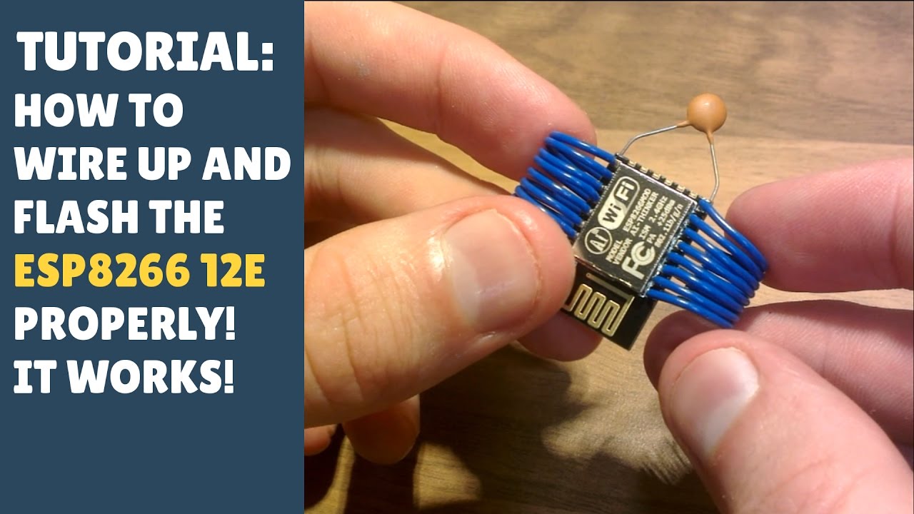
TUTORIAL: How to wire up and flash the ESP8266 12E properly! It works! (Arduino - Getting Started)
Показать описание
My website link for downloads (if any are present), etc:
Just a tutorial on how to get the ESP8266 12E to work properly. It's the most difficult module I've worked with to date and I finally feel as though I've cracked it. So I thought I'd share this with everyone so that they don't have to spend countless hours the way I did! :-)
NB:
The capacitors are used to reduce noise and also for stability - I'd say they are necessary! The resistors are pull up and pull down resistors, these are to prevent ambiguous signals from being read into the ESP8266.
 0:15:38
TUTORIAL: How to Wire up & Code an EEPROM with Arduino - Module (Part 1 - Theory)
 0:18:37
TUTORIAL: How to Wire up & Code an EEPROM with Arduino - Module (Part 2 - Wire Up & Coding)
 0:00:25
Electrical Panel Or Artwork? #tutorial
 0:01:37
How to connect switch with motor - AA Battery, Motor, Switch tutorial
 0:29:36
Ultimate Electricity Guide - Beginner To CHAD 2022 | Rust Tutorial
 0:03:54
How to Wire a 3-Way Switch
 0:06:57
HOUSE WIRING TUTORIAL-Basic Electrical Installation(Tagalog) | Local Electrician
 0:00:30
Wire Ferrules Tutorial #shorts #caraudio #bass #installation #subwoofer #amplifier
 0:01:00
Bina atm card ippb se phonepe me UPI PIN set kare india post payment Bank se Phonepe kaise banaye
 0:10:10
Single Phase Electricity Explained - wiring diagram energy meter
 0:09:11
How To Wire Up Your DC Model Railway / Railroad Layout - Tutorial Tuesday Episode 27
 0:07:05
Two Way Switching Explained - How to wire 2 way light switch
 0:04:35
Single Pole Switch Lighting Circuits - How to wire a light switch
 0:19:12
How to wire a single phase distribution board and load circuits - tutorial
 0:06:57
TUTORIAL: How to Wire up 1.8' TFT LCD Screen to NodeMCU ESP8266 - Easy! (Part 1/2)
 0:03:57
Soldering Tutorial for Beginners: Five Easy Steps
 0:10:05
TUTORIAL: How to Wire up and Code a TFT LCD Screen with ESP32 (Arduino) ST7735R
 0:01:00
Hair Rehab London Heatless Curls Hair Tutorial
 0:00:16
Electric light photocell sensor connection & diagram tutorial.
 0:13:38
TUTORIAL: Arduino Buttons! How they work, How to wire up and code. Back to Basics - 1.
 0:02:50
How to Install a New Circuit Breaker
 0:06:25
(#0033) 4-Wire Computer Fan Tutorial
 0:00:09
Tutorial on a magical ukulele (very easy)
 0:00:14
Heatless curls tutorial ❤️#youtube #hack #hair #hairtutorial #longhair
Комментарии