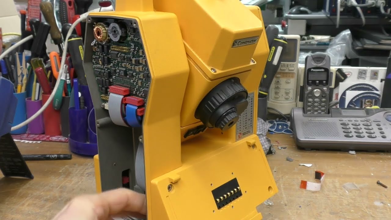
Spectra Precision Constructor total station teardown

preview_player
Показать описание
A look at some surveying gear
Рекомендации по теме
Комментарии
Автор

two videos within three days?? Did i miss chirstmas?

NIOC
Автор

It's great to have such an in-depth teardown of a total station, thanks Mike! The little widget on the top of the telescope is for the person operating the TS to get roughly in the right direction to point at the person with the staff - sight down the widget with both eyes open so the circle is full, and make coarse adjustments of the scope until the circle covers the top of the staff, then look through the scope and use the fine adjustment knobs to zero the crosshairs on the reflector. Normally the rodman's job is to hold the staff upright and in place and wait for the surveyor to shout that they've taken a reading. They need to keep an eye on the spirit level on the rod, and so won't be able to sight back to the TS. With staking-out (positioning the staff on a pre-computed point) the surveyor will set a known location and the TS will guide them up/down/left/right/back/forward, and they shout to the rodman to move until the reflector is in the right place. So in both cases the rodman's job is the more important - they need to choose the right location and keep as still as possible. The surveyor just needs one working eye, and the ability to press a few buttons.

The black and white part of the rotary encoder is for taking double-face shots. The surveyor will sight normally and take a reading, then they will flip the telescope and rotate the TS 180 degrees and take a second reading, the TS then averages the angles which eliminates any mechanical offset errors.

The ASCII chart is fascinating! The only thing I can think of is after looking at the control panel it only has numbers on it, so typing text requires the user to type in ASCII integers! That's batshit for '97! My TS is only a few years younger, and it has a speccy keyboard style alpha numeric keypad. While there's not a ton of text that needs typing - most of it can be set up in the office through the serial cable - there's enough to warrant a proper alpha keyboard.

merseyviking
Автор

We had a total station from about the same era at a job I worked on a few years ago.

The reason the front-panel/user-interface is removable is because it was effectively the storage disk for any measurements you took. The idea was you would detach it, carry it into the office, and plug it into a desktop PC which ran some accompanying software.

These things are extremely sensitive to level. The power-on process for the one we had involved it requiring you to do an extremely fine levelling procedure. You'd need to level the tripod using it's built-in level, and then that would get the overall level close enough for the internal sensor to work.

I spent some time writing software to get measurements from it. It had a ridiculously terrible serial interface, which would periodically lock-up and become unresponsive.

FakeName
Автор

finally you are back! come back more often, your videos on disassembling electronics are unique, I look forward to seeing you again!❤🎉

yuribochkarev
Автор

I was once given a Spectra Physics “Dial Grade” pipe alignment laser, as a teenager. A fascinating unit. Way, way before the internet I would work my way through the “Yellow pages” asking for old or discarded equipment (that’s how I got my first ever job at 16, as a TV & VCR apprentice).

I sat up all night and took the “Dial Grade” apart on the sitting room carpet. I was new to taking things apart back then in the 90s; it was all so magical and exciting. I didn’t have a torx driver (they were mysterious, exotic things) and so persisted in forcing the security screws undone with ingenuity and brute force.

I still CLEARLY remember the beautiful iridescent shimmer of the thick red HeNe laser beam, and the prettiness of the light reflecting off the coated lenses and dichroic glass prisms.

I would clip the leads to a car battery next to my bed and shine it out across the fields so it hit the wooded area about a mile away.

Beautiful memories.

unlokia
Автор

"The ASCII table can be used to enter alpha characters directly from the keyboard on instruments with a numerical keyboard. This can be done with the help of the (ASCII) key.", from "Pentax total station operating manual". Cheers !

brainfornothing
Автор

For the ASCII table - I've also seen them on old mobile road signs. The interface for entering the message is just a 3x4 keypad, so you enter ASCII directly. I assume people using this would also use those road signs.

AlexTaradov
Автор

Thank you for the tear down. Reduces my urge to tear mine apart. With careful battery change I think I can get some years of life out of mine when I learn to use it. The User interface on these units is abysmal with cryptic numeric command codes that made sense when the first total station was made and then the surveyors learnt the codes and did not want anything to change.

I'm reasonably sure that this was originally the Geodimeter brand that was purchased by Spectra Precision and then by Trimble.
The earlier units had a DE-9 connector and later a 4 pin so this case was perhaps made during the change over period.

The DE-9 connector has RS-232 or ASYNC TTL and power on non standard pins but not sure what the other contacts on the 6 way slip ring were for. I have a GDM424 Geodimeter unit that is before this one and this was probably one of the 500 or 600 series units, I think some model numbers were changed somewhat when the ownership changed (Trimble may have added 5000 to the model number).

The displays came in numeric and alphanumeric versions (cost cutting a keypad) so the ASCII table was to enable a numeric interface to easier enter alphanumeric names for the surveyed points.

The various units had either just calibration constants stored in the units with the battery backed ram or some of the 500, 4000 or 600 series units had the user interface program also RAM backed up. Earlier than the 400 units some had the fixed constants loaded into RAM memory as well that were the same for all units, perhaps they thought that some error in hardware or software could be compensated later by adjusting the speed of light to air density calibration. In the end all of these earlier units become doorstops if they loose their battery data because Trimble can no longer access the factory presets and except for one enthusiastic fellow nobody has any way to generate the calibration constants for the units. This amateur specialist might be happy to get copies of the ROMs for his collection.

The little telescopes are for coarse sighting for the operator. Some devices have a light beam they shine to the pole holder so he can point the prism (reflector) at the operator at the ranging station.

Some of the units with motorised sighting had detachable keyboards with radio link provisions, later units this was standard. The lone button was to take a reading when the unit was flipped over and the keypad was on the other side. Not much used on these because the factory calibration and the internal levelling (compensator) provided almost the full accuracy with just a single sighting. Some units could send voice signals to the pole holder via the measuring beam to an optical receiver attached to the pole with the prism.

I found a table that indicated some of the modulation frequencies used to calculate the ranging and while I did not follow why they were chosen it seems that there is some important reason. Here is a selection of the frequecies in Hz.
29970000
14985530
14985543
14984651
14984629
14985453
14987103
14987090
14983482
14985400
These were from 4 manufacturers including some Geodimeter but not these particular units where cryptic notes hints at the reason.

Note (i)
The carrier wavelength can vary between 850nm and 910nm due to the use of different types of diodes from various sources

Note(j)
The manufacturer selects the modulation frequency (~15 MHz) according to the actual carrier wavelength (as well as the 10M unit length) so that the same C and D terms can be used for all instruments

The "Terms of first velocity correction" indicated as C=275 and D=79.55 are the same for all but the very early Geodimeter total stations. Other vendors have different constants. Geodimeter also has their "Reference Refractive index" = 1.00275 for later units, other vendors have different values.

"?" gives a command list on some units.
Someone called mike1202 offered the following serial commands,
"OV*" - dump memory,
"RV, 100" - GDM model
"RV, 110" - loader time and date
"RV, 111"- GDM serial number
"RV, 113" - program version
Some others can clear all RAM memory

The open source project is on GITHUB user ROBOTS project GDM I think that may be the same user that provided the command list above.

KallePihlajasaari
Автор

The NE602 is a mixer amplifier chip used in radios so you're probably right that it works via some hetrodyne RF technique.

vincei
Автор

Hi Mike. Thanks for another really interesting vid. you always get some rarely available stuff and show us curious folks a really good look around inside and out.. from menial to mega complex, with good descriptions to help us understand what we are seeing. Love this channel. Thanks Mike. :)

Palmit_
Автор

I worked at Tripod Data Systems (now Trimble) and we sold quite a few of these, although they were branded as Nikon. I never got to take any apart though!

classicaudioadventures
Автор

The only reason I can think of for the ASCII table is that on average, it is likely faster to type in the B10 ASCII codes than it would be to type it in flip-phone texting style. The learning curve would be a lot higher though.

cameronwebster
Автор

regarding the strange positions of the pins in that photodiode package, it looks like that puts one pin in the center of the package, so I would guess the actual photodiode die is mounted to the face of that pin. That would provide some improvement in package parasitics versus the other method of mounting the die to a shelf in the can base and bonding it out to the pins. The latter method is more common in laser diodes for better thermal coupling of the die to the can, but means the diode is either electrically bonded to the can or is capacitively coupled to the can via an insulating layer. Putting the die on the face of a central pin isolates the diode entirely from the can without the capacitive coupling and eliminates one set of bond wires.

thavinator
Автор

The 'load' bearing on the foot probably isn't there for taking load, as the other bearing would be more than enough to do so. It's my guess it's for better precision by taking out any possible wobble from the other bearing.

johnvanderschee
Автор

as a surveyor, this was interesting to watch!

mitchmackenzie
Автор

Nice! That little laser diode probably pushes out a 100W or so in a few hundred nanoseconds.

LesLaboratory
Автор

It's called total station becauae it makes angular and distance measurements, error calculations and mapping calculations all within this single instrument in contrast with traditional geodesy methods.

deepblueskyshine
Автор

Very nice I've always wanted to see a total station tear-down. I've only read about inductosyn encoders, never seen one dismantled. For getting down to 1 second of arc it has an impressive lack of poles, so most of the resolution is from phase measurement. Yes I suspect the coarse optical is for absolute ambiguity removal. I wonder if they calibrate the encoder to remove its stationary non-idealities rather than relying on precision construction and alignment?

vkzay
Автор

The ASCII table is likely useful because they didn't have the option to press a number several times to get 'abc', 'def' etc, like on a 90'es cellphone (before T9 dictionaries). Even though the date codes say 1997 the design is likely much older

michaelthomsen
Автор

I've wanted a basic digital theodolite (don't really need GPS, but a rangefinder would be nice) for ages... despite not actually having a dire need for one. :) They can be quite handy, even indoors in a machine shop!

railgap