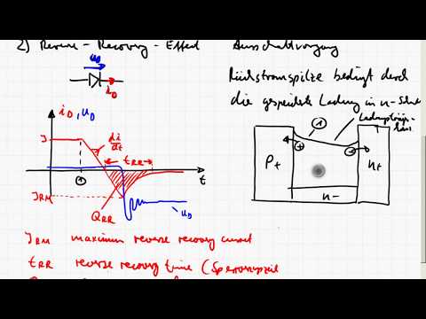
#201: Basics of Reverse Recovery Time in a Diode

preview_player
Показать описание
This video covers the basics of what the reverse recovery period is in a diode, some of the parameters that affect the reverse recovery time, and a simple measurement setup to observe the reverse recovery characteristic. Other related videos are:

A PIN Diode based T/R switch:

Basics of PIN Diodes and RF switching:

Basics of using diodes as switches:

Notes page:
Рекомендации по теме
Комментарии
Автор

I have been repairing a plug in power supply for my led illuminated magnifier. The output rectifier diode had cooked. As a temporary measure I put a 1N4007 diode in to check if there was basic functioning in the high voltage side.
I was shocked at how hot the diode got yet only passing 360mA or so.
It wasn't until a friend pointed out the slow recovery time was the cause that the penny dropped.
I harvested an ES1J off a dead phone charger - a fast recovery rectifier and everything worked fine.
Thank you for your very helpful demonstration.

stevejagger
Автор

I was having trouble with my zero-crossing detector because of this. We always have to learn the hard way that these are semi-conductors! Semi means they only do part of what you think they should do. Thanks for taking the time to explain this to us all.

whitefields
Автор

Understood what is diode reverse recovery time from this video. Spend enough time in my academic books, but was not able to understand the concept. Thanks for the video.

akhilgeorge
Автор

Thanks for the video! It needs to be emphasized that this test method is valid only for small-signal diodes. High current rectifiers (1A - 3A average If) can't be properly tested at low currents like this. A 1N4007 can measure nearly the same as a 200nS fast recovery rectifier with 10 - 20mA. It's only when current is increased above 100mA or so that the difference in speed becomes apparent.

TriodeLuvr
Автор

Good as always. I'm glad you showed a 914 and a schottky too.

KX
Автор

thank you for the video! it is very helpful. I especially like how you introduces things on paper and experimental results !!!

trayennhuphan
Автор

I was hoping that you would plug in a Drift Step Recovery Diode at the end of your video.Once, I had an old Russian PN rectifier diode, that was so poorly manufactured that the boundary between the P and N region was very diffused and that made it an excellent DSRD.  It was snapping off in under 1ns with 200A of reverse current flowing through it which allowed me to generate kW nanopulses with it.  Great stuff!

amciaapple
Автор

Thanks! You always have the best EE tutorial videos!

AppliedScience
Автор

Whenever there is a topic I'm looking for more info on in electronics I first go to w2aew, this is beautiful and stuff that I don't even have in my textbooks

industrialdonut
Автор

In one of my projects (a big power supply) I have a bridge rectifier consisting of 4 huge diodes in a bridge format....
Although it is of no worry to me the ouput after the regulator does have a very low level (a few mV) of commutation noise from the diodes. Once again a very well presented video, always food for thought...

davidlisney
Автор

The behavior of the schottky diode is interesting, perhaps that could be a future subject?
Another great video!

Corgitronics
Автор

So well explained that I have now understood much more about diodes than ever before in one go! Amazing your introduction Alan!!!!

kristhetrader
Автор

A great clip again.

Now that I think of it, that is why we can use varactors in VCOs with higher AC voltage than reverse DC bias of varactors.
Of course, here you are talking about forward bias charge storage, in varactors it is reverse bias charge storage. (ie. diffusion capacitance vs. depletion capacitance)

However, in my opinion the best way to see if you have a pin diode or not is to figure out its doping profile. You can do this by incrementally biasing the diode, and measuring its capacitance and relating it to its doping profile. If you want to do this you should bias the diode from just below to turn on voltage and slowly decrease the bias voltage up about about 1/3 of reverse breakdown voltage measuring capacitance at each step and inferring the doping, and create a complete doping profile.

aduedc
Автор

Beauty of analog circuit is time resistant. Keep on going revealing this beauty to all of us!
I'm becoming to be addicted :)

codijack
Автор

Thank you for all the time that you spend making these videos. I appreciate it!

kbskb
Автор

Can't thank you enough for showing what goes on Inside components!

TonyButchT
Автор

Thanks a lot for very clear explanation. After going through lot of articles I did not get things cleared. But you did it very nicely. Thanks for your good work. Wish you the best.

pradeeplanka
Автор

That is quite a dramatic demonstration of "reverse recovery" time for various types of diodes. Before watching your video, reverse recovery time was just a number on the spec sheet that was respected, but seeing it "on the screen' really brought the meaning home. Thank you. WA9KZY.

warrencurry
Автор

nice, clean fixture and excellent explanation

stevefranks
Автор

Thanks Alan, very timely as I was just sorting a parts bin of PIN diodes and came across some VERY old ones I'd gotten from Hamtronics years ago that I don't have a data sheet for (neither did they). At least now I can compare these to others that I have the data sheets for and at least get a feel for how they match up to known units. 73 - Dino KL0S

PapasDino
welcome to shbcf.ru