filmov
tv
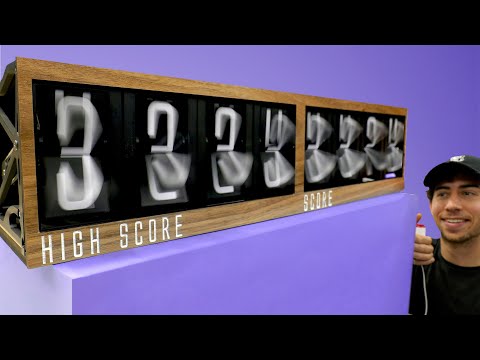
Mechanical 7 Segment Display Clock Using An Arduino & 28 Servos

Показать описание
In this project, I’ll be showing you how to build a mechanical 7 segment display clock which is driven by 28 servos controlled by an Arduino Uno. Time is kept using a DS1302 real time clock module and each servo is independently controlled using two PCA9685 16 channel servo drivers to expand the Arduino’s PWM IO over the I2C interface.
Parts List and Purchase Links:
If you’ve got any suggestions for Arduino projects or tutorials, let me know in the comments section below.
Parts List and Purchase Links:
If you’ve got any suggestions for Arduino projects or tutorials, let me know in the comments section below.
 0:10:51
Mechanical 7 Segment Display Clock Using An Arduino & 28 Servos
 0:14:04
Testing 9 Different Mechanical Displays
 0:00:51
“Practical” 7 Segment Module Uses
 0:00:43
Lego Mechanical Fourteen-Segment Display
 0:00:44
Rack Driven 7 Segment Display
 0:07:58
The Rack Driven Mechanical 7 Segment Display - How To Assemble
 0:00:38
Mechanical 7 Segment Display
 0:00:14
Mechanical seven segment display (alternate angle) #b3d
 0:04:24
Mechanical seven segment clock (Clock 7)
 0:01:19
Digital clock with mechanical 7-segment display units
 0:01:24
Mechanical 7 segment display clock
 0:16:55
7 Segment Counter v3.0, Tutorial, 3D Printed, STL Files Link
 0:01:07
Eptaora
 0:04:21
Parts For The Mechanical 7 Segment Display Clock
 0:04:51
Telechron Mechanical Seven Segment Display Clock
 0:16:36
7 Segment Counter v2.0 Tutorial, 3D Printed, STL Files Link
 0:00:26
Mechanical 7 Segments display clock - Post Tenebras Lab
 0:00:22
#arduino powered Mechanical Clock 7-segment Display with Servo Motors #engineering #tme #diy
 0:00:21
Mechanical Seven Segment Display Digit
 0:05:46
7 Segment Clock, Digital, Mechanical, 3D Printed.
 0:00:32
Mechanical Seven Segment Display POC
 0:17:26
NeoPixel 7 Segment Display Clock Update
 0:01:55
How to build a mechanical 7 segment display clock | DeepSea Developments
 0:00:28
Mechanical 16 segment display
Комментарии