filmov
tv
Air Entrainment Explained

Показать описание
Sections :
00:00 – Introduction
01:02 – Airlock Explanation
02:29 – Airlock Causes
04:34 – Difference Between Airlock and Mild Cavitation
05:29 – Tips to Control Airlock
10:39 - Conclusion
Air Entrainment – A distant cousin of Cavitation
Imagine that you are stuck in a locked room, wanting to go out but there is no escape. How much torture would that be for you? That is the amount of torture that the liquid experiences when air or vapor gets entrapped in a pump system.
Let us discuss about Airlock, how it occurs in the pump system, what are its causes and effects and 4 tips on how to control them, so that you can consider applying them in your pump system rightaway.
References:
Suction Side Problems – Gas Entrainment by James. H. Ingram
Air Release Valve
Vortex Impeller
Inducer
Side Channel Pump
Side Channel Impeller
Choi, Won & Yoo, Il & Park, Mu & Chung, Myung. (2013). Experimental study on the effect of blade angle on regenerative pump performance. Proceedings of the Institution of Mechanical Engineers, Part A: Journal of Power and Energy. 227. 585-592. 10.1177/0957650913487731.
Side Channel Operating Principle - Sero Pumps
Kryptonite
CC0 - Audio :
Vortex Diagram – Pump World 1978 Edititon
Attributions: Licensed under CC
 0:11:47
Air Entrainment Explained
 0:01:54
What Is Air Entrained Concrete?
 0:01:32
Air Entrainment Explained Teaser
 0:01:50
What is Air Entrained Concrete? || Types of Concrete #7
 0:00:41
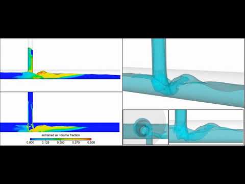
Air Entrainment Analysis | FLOW-3D HYDRO
 0:09:55
Why do we NEED air bubbles in concrete? | air entrained concrete
 0:05:00
Air Entrained Concrete
 0:00:25
Air Entrainment Demonstration
 1:04:04
Air Entrainment Analysis | FLOW-3D Webinar
 0:20:55
Admixtures for Concrete - What is an Air Entraining Admixture?
 0:03:20
Air Entrainment Experiments
 0:06:35
Air Entrainment
 0:25:24
Why do you lose air volume when pumping air entrained concrete and why does the air come back?
 0:00:32
Scour and air entrainment analysis of a large dam | FLOW-3D HYDRO
 0:01:44
Bernoulli’s Principle
 0:08:09
How to make concrete last 100 years
 0:21:28
Air Entrainment
 0:00:22
Air entrainment in a vertical drop shaft | FLOW-3D HYDRO
 0:00:16
Die casting mold air entrainment analysis and optimization of motor control unit die casting Housing
 0:01:40
Triterpene (liquid) Air-entraining agent test
 0:02:41
ACI ASTM C231 - Air Content: Pressure Method 2019
 0:04:44
Air Entrainment Computational Fluid Dynamics (CFD) Analysis
 0:01:42
Air-entrainment rapid air rest for concrete
 0:01:19
2021-07 - Hydraulic Jump and Air Entrainment in Pipeline with Vertical Bend
Комментарии