filmov
tv
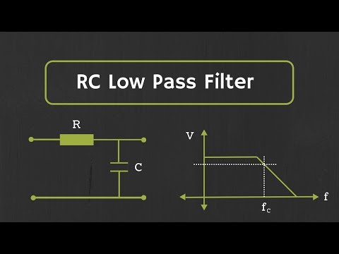
RC Low Pass Filter Explained (with Speaker Example)
Показать описание
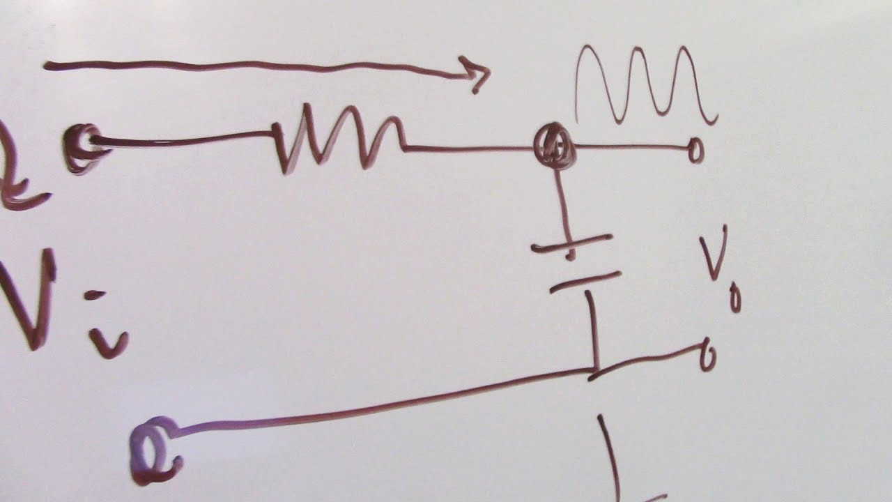
In this video, I go over the concept of RC low pass filters. This includes the theory as well as the application. I go through the basic RC low pass filter circuit design, and go into detail about the components such as the capacitor and the resistor. I put the theory to the test by wiring up the filter to a speaker and an audio source. Hopefully, you have enjoyed the video! If you enjoy these types of videos then let me know! There is also more engineering videos on my channel already, so be sure to check those out too! :)
**MUSIC**
Licensed under Creative Commons: By Attribution 3.0
**MUSIC**
Licensed under Creative Commons: By Attribution 3.0
 0:15:18
RC Low Pass Filter Explained
 0:18:28
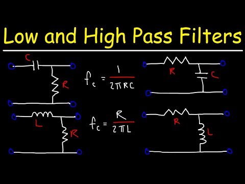
Low Pass Filters and High Pass Filters - RC and RL Circuits
 0:05:55
RC low pass filter explained | Passive filter | Electrical Engineering
 0:08:33
Passive RC low pass filter tutorial!
 0:17:11
RC Low pass filter Explained with Example.
 0:08:30
RC Low Pass Filter Explained (with Speaker Example)
 0:08:37
How Low Pass Filters Work
 0:01:54
RC Low-Pass Filter (Time-Domain and Frequency-Domain Explained)
 0:06:54
RC low pass filter explained in detail | Passive filter | Electrical Engineering
 0:05:32
How a Low Pass Filter Works
 0:45:40
RC Low-Pass Filter Deep-Dive - Phil's Lab #118
 0:05:40
What is a Low Pass Filter?
 0:15:17
Low-pass and High-pass Filters (Explanation and Examples)
 0:15:21
RC low pass filter explained with LTSpice
 0:00:13
How passive low pass filter work in electronics circuit
 0:00:33
Filter Types Explained In 30 Seconds
 0:03:51
The 1st order RC low-pass filter
 0:00:15
high-pass vs low-pass
 0:01:25
Low pass, High pass, Band pass and Band stop filters explained
 0:00:16
RC Filters #electronicseducation #electronicsrd #filter #rc #lpf #resistor #capacitor #circuit #hpf
 0:00:09
How Active Low pass filter work in electronics circuit
 0:05:33
RC High Pass Filter Explained | Passive filter | Electrical Engineering
 0:31:56
Filters Tutorial 2: 1st Order RC Low Pass Filters
 0:02:52
RC Low Pass Filter on Breadboard and Oscilloscope #lowpassfilter
Комментарии