filmov
tv
High-Ratio 3D Printer EXTRUDERS – MUST HAVE? or STUPID?

Показать описание
👉🏻 In this video I am testing if high ratio 3D printer extruders are viable or it is just stupid as currently nobody in the 3D printing market uses ratios that are so high. I made multiple test prints, comparisons, and full calculations to determine that and the results might surprise you.
📋 RELATED ITEMS TO THE VIDEO (Affiliate)
📷 VIDEO SHOT ON:
📢 OTHER MENTIONED THINGS:
🕗 TIMESTAMPS:
00:00 - The question
01:06 - The 21.6:1 ratio extruder
01.46 - So much prep work...
03:24 - POM vs LR, input shaping, test prints, and first layer consistency
04:00 - TESTING & EXPLANATION
08:55 - Final thoughts
🔗 YOU CAN FOLLOW ME:
#AnkerMakeM5C #Extruder #TEST
 0:09:57
High-Ratio 3D Printer EXTRUDERS – MUST HAVE? or STUPID?
 0:07:46
SMALL GEAR Extruders are NOT VIABLE ANYMORE?
 0:31:43
Last Hotend and Extruder Upgrade You’ll Ever Need?
 0:02:07
Dyze Design Extruders Overview: High-Flow Extruders For Large-Scale 3D Printing
 0:00:16
Sprite Exturder SE | 3.5:1 Gear Reduction Ratio Provides You a Smoother Printing
 0:03:29
Tech Breakdown: Bondtech 3D Printer Extruders
 0:02:28
Titan: High Performance Extruder from E3D
 0:08:11
How To Calibrate E-steps and Flow Rate for Ender 3
 0:09:24
E Step Calibration Vs Flow
 0:21:25
How to find the best HotEnd? - Ultimate HotEnd Testing - Episode #1
 0:16:06
Bowden 3d Printer Extruder Vs. Direct Drive
 0:12:22
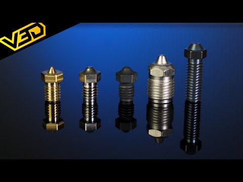
3D Printer Nozzles - Everything you need to know
 0:14:21
Good/Better/Best: Which Hotend is Right for You?
 0:14:17
The TRUTH about CHT Clone Nozzles! - Are High Flow 3D Printer Nozzles worth it?
 0:07:42
How To Tune The Flow Rate On Your 3D Printer!
 0:00:15
Creality K1 Max: Unleashing 600mm/s Speed and Smart Printing!
 0:11:38
// HOW TO // Extruder + Flow Rate Calibration
 0:00:25
$13/KG ELEGOO RAPID PETG @ElegooOfficial
 0:00:16
Elegoo Neptune 4 Pro #3dprinter #dprinting #elegooneptune4pro
 0:00:16
Lightweight Nema 8 Direct drive Extruder Prototype for High flow Dragon hotend V1 #3dprinting #3d
 0:01:24
The H2D isn’t worth it
 0:01:52
Bondtech BMG Extruder // 3D Printing Product Highlights and Review
 0:00:11
Ender 3 Printer Upgrades you can PRINT at HOME
 0:00:12
hotend first flow test #3d #3dprinter #corexy #cnc #diy #workshop #garage #project #design
Комментарии