filmov
tv
The circuit diagram shown here corresponds to the logic gate

Показать описание
#ASDPhysicsAcademy
#AkashSir_Physics
#ASDSir_Physics
DPQ-3: Logic Gates NEET 2019 Class 12th Physics Question:-
The circuit diagram shown here corresponds to the logic gate,
Follow Me on:
#AkashSir_Physics
#ASDSir_Physics
DPQ-3: Logic Gates NEET 2019 Class 12th Physics Question:-
The circuit diagram shown here corresponds to the logic gate,
Follow Me on:
 0:02:23
The circuit diagram shown here corresponds to the logic gate
 0:11:03
The circuit diagram shown here corresponding to the logic gate
 0:07:07
, , The circuit diagram shown here corresponds to the logic gate, - (1) NOR (2) AND - (3) OR,
 0:01:40
The correct Boolean operation represented by the circuit diagram drawn is :
 0:01:46
The correct Boolean operation represented by the circuit diagram dr...
 0:01:03
Which of the following logic expressions represents the logic diagram shown?
 0:03:36
The correct boolean operation represented by the circuit diagram drawn is [NEET 2019] (a) NOR (b)...
 0:03:10
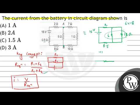
The current from the battery in circuit diagram shown is (A) \( 1 \mathrm{~A} \) (B) \( 2 A \) (...
 0:00:59
555 Timer Internal One And Two Thirds Voltage Divider Explained #short #shorts #electronics
 0:07:55
Consider the following circuit diagram
 0:02:32
In the circuit diagram shown in the adjoining figure, the resultant capacitance betw
 0:03:44
Circuit Diagram - How to understand and read a circuit diagram?
 0:03:48
Circuit diagram - Simple circuits | Electricity and Circuits | Don't Memorise
 0:23:48
Kirchhoff's Voltage Law - KVL Circuits, Loop Rule & Ohm's Law - Series Circuits, Physi...
 0:00:14
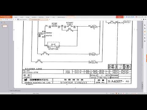
DOL Starter Circuit Diagram with Motor Connection.
 0:06:47
The circuit diagram below shows a battery of emf 12 V and internal resistance 1.5 Ω connected ...
 0:05:28
Wiring Diagram 2 Plate Method How to Add Multiple (More) LED Downlights (Spotlights) to Your Circuit
 0:06:48
Electric circuit diagram explanation for electrical engineer in English
 0:08:18
Learn CPU circuit diagram troubleshooting - Processor circuit power rail VCC_Core
 0:05:18
3 PIR's Lighting Control - Wiring Diagram Part 2
 0:29:56
Hoist/crane motor control circuit diagram and wiring installation, start stop push button.
 0:06:45
AQA GCSE Physics - Standard Circuit Diagram Symbols
 0:01:29
37. The circuit diagram shows a capacitor that is charged by the battery after the switch is connec
 0:00:27
AND GATE | Symbol | Truth Table | Circuit Diagram
Комментарии