filmov
tv
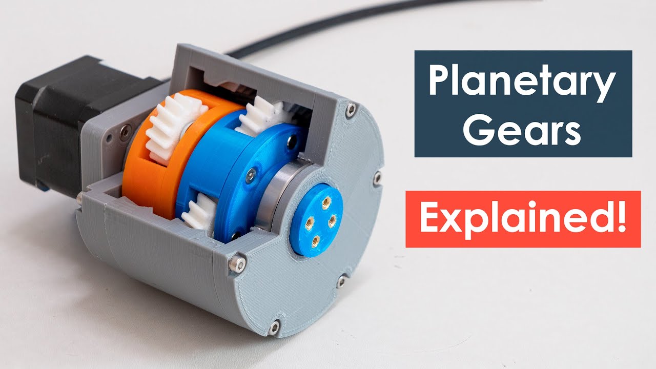
How Planetary Gears Work | 3D Printed Planetary Gearbox Design and Test
Показать описание
Measuring tools used in the video (affiliate links):
Amazon:
AliExpress
Parts list (check website article for full list, affiliate links):
AliExpress:
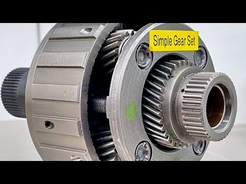
In this video we will learn what is a planetary gear set and how it works, as well as explain how to design our own planetary gearbox and 3D print it so we can see it in real life and better understand how it works. At the end of the video, we will also do some backlash and torque tests to see how well it can perform being a 3D printed gearbox.
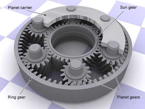
00:00 What is Planetary Gear Set?
03:37 Two-Stage Planetary Gearbox Design
06:56 Design Rules
08:38 Gears Module
09:15 Designing the Gearbox
12:45 3D Printing
13:25 Assembling
17:22 Backlash Test
19:22 Torque Test
Like my page on Facebook:
 0:04:53
Understanding PLANETARY GEAR set !
 0:09:59
What makes planetary gearboxes so amazing?
 0:06:01
Easy 5 Minute Crash Course In How Planetary Gears Work
 0:21:12
How Planetary Gears Work | 3D Printed Planetary Gearbox Design and Test
 0:06:04
Why Planetary Gear set is really amazing?
 0:13:55
HOW IT WORKS: Planetary Gears
 0:03:33
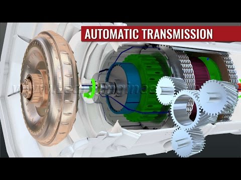
How do automatic transmissions work?
 0:00:21
How does a planetary gearbox work?
 0:00:31
3 stage planetary Gearbox
 0:01:58
How Automatic Transmissions Work! (Planetary gear)
 0:00:26
planetary gears in motion
 0:51:43
Planetary Gear Set Operation - AUSV 2520
 0:01:00
Visually demonstrating planetary gear set ratios
 0:00:21
Epicyclic Gearing (Planetary Gearbox)
 0:07:36
Automatic Transmission, How it works?
 0:08:43
Automatic Transmission Planetary Gear Sets
 0:00:11
planetary gear reducer
 0:05:15
Calculating gear ratios within a planetary gear set
 0:00:16
planetary gear working in excavator
 0:05:06
Automatic Transmission, How it works?
 0:04:07
How the Toyota hybrid planetary gearbox works (P410) - Academic laboratory at PUT
 0:20:24
Planetary Gearset - How it works (automatic transmission gears) (4L60E)
 0:04:45
PLANETARY GEARS why they are pretty cool
 0:08:25
How this magnetic transmission works?
Комментарии