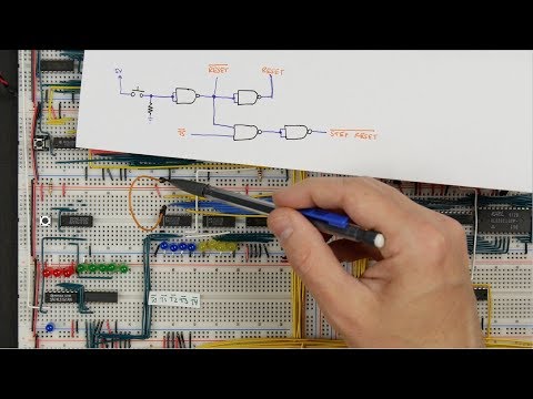
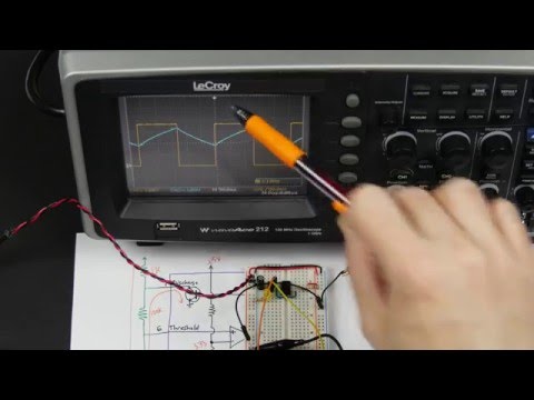
8-bit CPU reset circuit and power supply tips

preview_player
Показать описание


Рекомендации по теме
Комментарии
Автор

This deep into the series, I'm starting to come up with ideas before Ben presents them. While watching the previous video, I was thinking "I'd wire up a reset button for everything, " and now he's doing that. I also had an idea for what to do with the unused control line, and then he started alluding to a future use for it. It's a testament to what a phenomenal teacher Ben is. I'm not just watching, I'm learning, because I have a great teacher. These videos are priceless!

fweephokus
Автор

building myself a copy of this computer, bought the pieces on the weekend and built the clock today

thanks for making these videos, so far this is a lot of fun and has reinvigorated my interest in electronics

Crushnaut
Автор

soo many blinking lights, soo satisfying @10:50

barmetler
Автор

Speaking of power tips, I think this computer is in desperate need of bypass caps. I think this will help a lot of people who are facing power distribution issues. Btw I'm a big fan of this series; you're doing an excellent job presenting every step of the way with great clarity.

jtsiomb
Автор

Thanks loads. You just solved some of my confusion. I've been watching this whole series and decided to get a breadboard kit to play around with. I also finally got around to assembling the Three Fives kit and was trying to use that to make a LED blinker as a first project. Aside from the breadboard kit coming with "100 nF" capacitors that measure out as 47 nF, I hadn't realized yet that this breadboard had split power rails.

Orxenhorf
Автор

Man, you gave me more about this things than CS university ... Thanks <3 :)

jozef_kascak
Автор

I'm really enjoying this series, but one thing I keep hoping you're going to do is to use that spare bit in your microcode rom to implement a microinstruction counter reset signal so that at the last step of each instruction, your microcode rom signals that counter to reset so that architecturally when you're done with an instruction you're back at T0 again (giving you instructions that complete in differing numbers of clock cycles as well as no need to ever manually reset the microinstruction counter since HLT will do it as well and simplifying your reset logic overall).

nilk
Автор

Excellent! Also - a note on the cheap MB-102s - there may be two 'flavours' of them, one packaged with a black top (which has the weird numbering, the power rail breaks, the reverse printing, the difficult insertion) and one packaged with a blue top (which has none of these issues).

LemoUtan
Автор

I just have to say: I am in awe... These videos you made about building a computer from scratch are quite inspirational and make me understand how a cpu can be build and customized.
Please keep up the good work!

alexandermaasland
Автор

I always wondered why the first vacuum tube based computers had so many lights. Now I understand.

lightdark
Автор

Every time I have been doing some projects with " TTL logic " I have allways used decoupling capacitors, mainly to avoid power starvation.
It's a Really nice Tutorial You got put together there, I enjoyed it wery much.
Thank You wery much. Keep up the good work

Firefly
Автор

can you add an IO module, to see how the computer interact with the outside world. keep the good work ^^

younessamr
Автор

YOU DON'T NEED POWER DISTRIBUTION PROBLEMS. They can give you wildly unrepeatable results. I recommend running power on bus bars outside of the grid with power and ground delivered to the prototyping boards with the 0.025" square pins as you mentioned. You can make bus bars with 0.062" double-clad FR-4 PC board material which will slide down easily between the rows of your 0.025" square pins. This also gives you an excellent platform for mounting bypass capacitors, which I see a few on your board.

benthere
Автор

This was a great journey. I enjoyed every bit of it. Thanks for putting all things togeter in a consistent way, so it was easy to folow through. Good luck with other projects.

koolatrimr
Автор

Thank you for these fantastic videos. I am an electrical contractor, built many control panels etc and spent many years as a kid writing basic programs for the C64 and the BBC micro. Never managed to really blur these lines and understand electronics and the basic principals of how computers work. Until now. I plan to order the bits and probably build this on boards and put in a nice case with lots of flashing lights and switches on the front :) Thanks again for your fantastic work.

GazzJ
Автор

It's interesting that the MB-102 boards you received are the low-quality boards with breaks in the middle, because the latest boards I purchased are exactly the same brand and even came in exactly the same package with exactly the same brand markings, but they're better quality than the ones you're showing and with continuous power rails and more consistent printing (although the numbers are still not quite aligned properly).

The boards I got still aren't the best quality, but they're acceptable if you're willing to overlook their shortcomings.

I posted a link to the eBay listing on a previous video. The seller offers boards, a power supply plugin board and jumper cables, and offers them in a few combinations too.

JasonMasters
Автор

I was really hoping that the resetting of the control logic instruction step counter would be done in the EEPROM instead of hard-wiring to T5. This would have enabled real various length operations and allowed a bit of cycle optimization. This could be done with the second EPROM which has an unused IO pin and that could be connected to the instruction microcode step counter reset line. You would program the EEPROM accordingly and this would allow, for example, LDA microcode to reset/finish at T4 and ADD to end/reset at T5. Basically just put a 1 in the EPROM at the end of each instruction microcode to reset the instruction step counter.

Mr_ToR
Автор

If possible, Im going to give you 2 likes for each of your videos. Nice series Ben! It is really that good and educating, while also being interactive.

vierikristianto
Автор

For the asynchronous reset on the step-counter, you could tie all the inputs to LOW, and use "load" as the reset, which makes this synchronous to the clock too :) - Then you have a "step counter reset line" to work with.

SteveYoung
Автор

I can't wait for the next chapter, I don't have idea what next but allways something excelent and with an perfect explanation. Maybe the next step could be to add more instructions but I think is time to make a new programming system, maybe with a keypad.

jetraid