filmov
tv
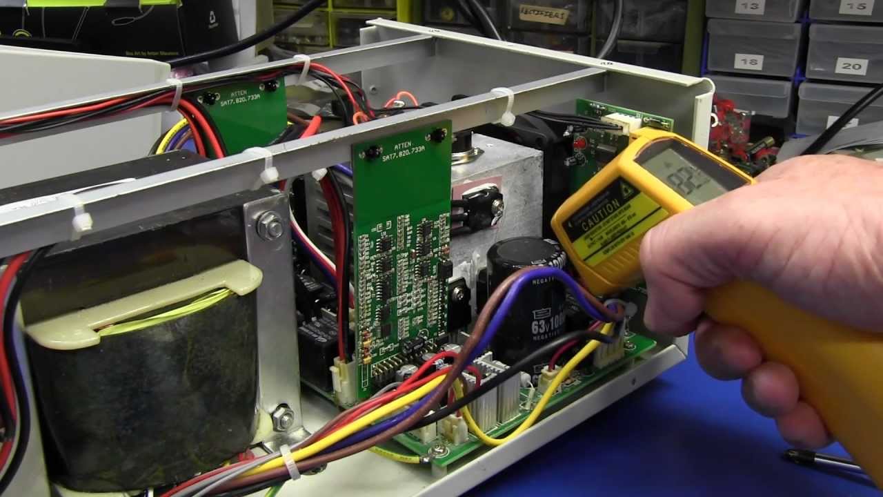
EEVblog #440 - Atten PPS3205T-3S Triple Output Power Supply Teardown
Показать описание
Inside the Atten PPS3205T-3S 3 output precision laboratory bench power supply.
EEVblog Main Web Site:
EEVblog Amazon Store:
Donations:
Projects:
Electronics Info Wiki:
EEVblog Main Web Site:
EEVblog Amazon Store:
Donations:
Projects:
Electronics Info Wiki:
 0:45:47
EEVblog #440 - Atten PPS3205T-3S Triple Output Power Supply Teardown
 0:59:41
EEVblog #439 - Atten PPS3205T-3S Triple Output Power Supply Review
 0:17:22
EEVblog #540 - HP35670A DSA Repair - Part 3
 0:29:10
EEVblog #272 - Manson 9400 40A 3-15V Switchmode PSU Teardown
 0:16:33
EEVblog #166 - HP Agilent E3610A Lab Power Supply
 0:40:43
EEVblog #449 - Absopulse VFC500 Variable Frequency Converter Teardown
 0:05:56
EEVBlog - Bits und so #451
 0:31:50
EEVblog #828 - Siglent SPD3303X Precision Lab PSU Teardown
 0:02:07
Atten PPS3005S DC Power Supply Fix
 0:16:24
EEVblog #357 - USB Supply Power-up Testing
 0:03:50
EEVblog #404 - Korad PSU Followup
 4:31:00
EEVblog #400 - 400th Live Show
 0:18:05
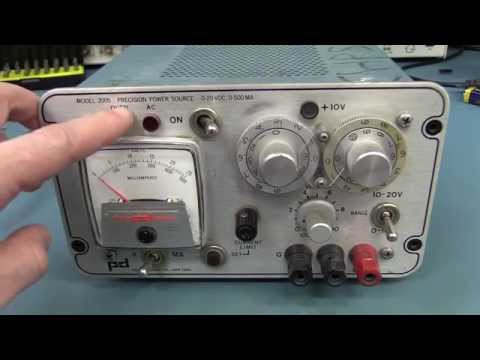
EEVblog #649 - Power Designs 2005 PSU Teardown
 0:12:23
EEVblog #445 - Fluke Contest Draw
 0:20:50
EEVblog #435 - 3D Rocker Teardown
 0:16:25
KORAD KA3305D Digital control dc power supply psu teardown + failure + troubleshoot
 0:26:47
EEVblog #511 - Rigol DP832 Power Supply Teardown
 0:33:18
EEVblog #814 - Keysight N8762A 600V 5100W PSU Teardown
 0:43:42
EEVblog #509 - Rigol DP832 Lab Power Supply
 0:29:41
EEVblog #419 - Thermocouple Tutorial
 0:28:55
ITECH IT6322 Triple-power supply review
 0:54:46
Breaking Down Medical Equipment Part 1 - ASMR - Scrap Breakdown - Recycling
 0:16:47
BK Precision 0-30v 3amp Bench DC Power Supply Review
 0:10:31
Club Jameco Dual Adjustable Power Supply Kit
Комментарии