filmov
tv
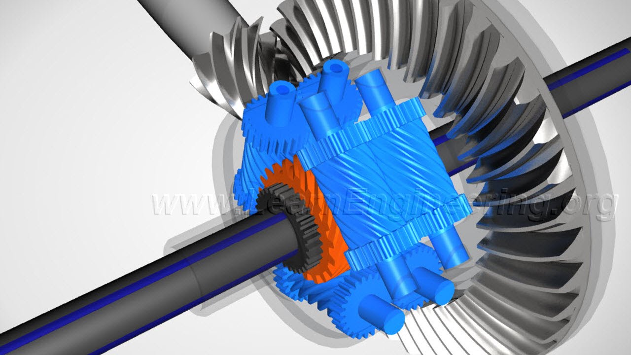
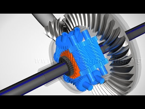
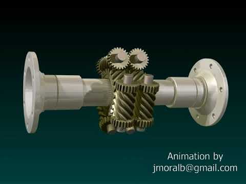
Torsen Differential, How it works ?
Показать описание
The working of Torsen differential is elaborately explained in this video with help of animation.
 0:05:22
Torsen Differential, How it works ?
 0:04:20
What's a Torsen limited slip differential?
 0:00:17
Torsen differential working with video tutorial
 0:10:47
Torsen Limited Slip Differential - Explained
 0:03:45
TORSEN vs OPEN DIFFERENTIAL - TORQUE SPLIT simplified animation model
 0:02:25
Kenny's Thoughts on Torsen Differentials
 0:00:16
16. Torsen differential || how does a gearbox work
 0:12:26
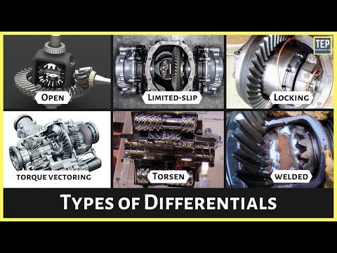
How a Differential Works | Types of Differentials Explained
 0:02:57
Miata Torsen T-2 limited slip differential assembling
 0:00:56
What's a Torsen™ differential? Why is it so cool? #shorts
 0:00:40
Diferencial Torsen (Autoblocante) / Self-locking Torsen Differential
 0:00:27
How it works TORSEN DIFFERENTIAL || Design 3D || Library
 0:04:56
Understanding Limited Slip Differential
 0:01:01
Audi Torsen differential - technical animation
 0:05:41
Torque Vectoring Differential - Explained
 0:00:40
torsen differential full animation
 0:01:36
TORSEN DIFFERENTIAL || DISADVANTAGE || ADVANTAGE || WORKING ||
 0:09:13
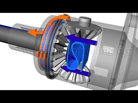
DIFFERENTIALS | How They Work
 0:04:47
Differential | How does it work?
 0:00:27
Open diff VS LSD conversion set by RacingDiffs | BMW Z4 donuts
 0:00:46
Torsen T1 - Torque Bias Ratio test rig
 0:01:59
Difference Between Limited Slip Differential And Torsen Differential?
 0:05:27
Torsen vs standard differential from LEGO - explained
 0:15:08
Audi quattro AWD DIFFERENCES - Torsen vs Centre Differential vs Haldex vs Ultra
Комментарии