filmov
tv
1-Wire – Through the Looking Glass (Scope) and Down the Rabbit Hole (Bit Level)

Показать описание
With an Arduino and some DS18B20 temperature sensors as example …
↓↓↓ Complete description, time index and links below ↓↓↓
Like many people on this planet I have a lot of time on my hands right now (that virus thing). So why not do a bit by bit analysis of what’s happening on a 1-Wire bus? Maybe I – or you – can gain some insights into the meaning of life.
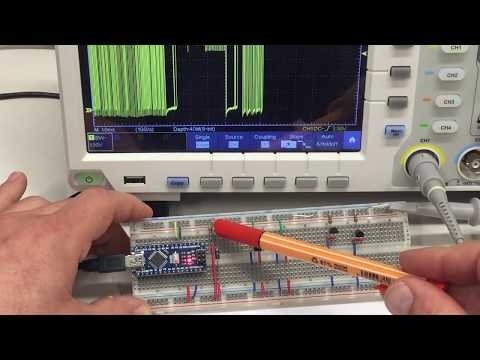
And some insights I gained: How to probe a 1-Wire bus with the scope (differentiating between slave and master signals, hard pull-up and resistor pull-up), how the 1-Wire search (“Search ROM”) works (9 minutes at 29:06) and much more.
►Intro
00:00 Intro – be warned, it will get ugly (and watch the previous video first)
►Operating a parasite powered 1-Wire bus
01:30 Overview – what’s on the breadboard and a quick recap of the code
03:41 Ones and zeros – on the 1-Wire bus, it’s a question of time(ing)
06:38 Broadcasting a command – “Skip ROM” [CCh] and “Convert T” [44h]
08:12 Preparing for a command – master reset and clients present, real long lows
10:24 Voltage levels – what’s high, what’s low and difference between master and slaves
14:14 Probing trickery – a diode and some resistors make the bus easy to probe
16:42 Addressing a slave – “Match ROM” [55h] followed by a 64-bit slave ROM address
21:24 Command for that slave – “Read Scratchpad” [BEh] followed by data from the slave
23:54 Repeat for another slave – nothing new here but for a DallasTemperature lib oddity
25:34 Noise while bus is high – slaves pulling parasite power through pull-up resistor
►Initializing a 1-Wire bus
26:46 Overview – discovering slaves on the bus, their addresses, power mode and details
29:06 1-Wire search – “Search ROM” [F0h] for implementing a binary tree search
38:16 Slave power mode – first slave addressed [55h] and “Read Power Supply” [B4h]
40:45 Slave details – first slave addressed [55h] and its scratchpad read [BEh]
41:45 Repetitive stuff – more of the same over and over again
45:04 Bus activity summary – of all the bus activity including the repetitive stuff
45:53 Code review – redundancies, oddities and maybe a bug
►Differences to a direct powered 1-Wire bus
47:54 Overview – changes on the breadboard and in the probing
49:18 Difference – “Read Power Supply” [B4h], and it differs from the datasheet too
►Timing considerations
51:23 Recovery time – depends on a lot of things, including temperature
►Summary
54:37 Three main point – parasite vs direct power, 1-Wire is easy and trust no one
#robertssmorgasbord #tutorials #tutorial #how-to #Arduino #temperature #temperaturesensor #bus #dallas
↓↓↓ Complete description, time index and links below ↓↓↓
Like many people on this planet I have a lot of time on my hands right now (that virus thing). So why not do a bit by bit analysis of what’s happening on a 1-Wire bus? Maybe I – or you – can gain some insights into the meaning of life.
And some insights I gained: How to probe a 1-Wire bus with the scope (differentiating between slave and master signals, hard pull-up and resistor pull-up), how the 1-Wire search (“Search ROM”) works (9 minutes at 29:06) and much more.
►Intro
00:00 Intro – be warned, it will get ugly (and watch the previous video first)
►Operating a parasite powered 1-Wire bus
01:30 Overview – what’s on the breadboard and a quick recap of the code
03:41 Ones and zeros – on the 1-Wire bus, it’s a question of time(ing)
06:38 Broadcasting a command – “Skip ROM” [CCh] and “Convert T” [44h]
08:12 Preparing for a command – master reset and clients present, real long lows
10:24 Voltage levels – what’s high, what’s low and difference between master and slaves
14:14 Probing trickery – a diode and some resistors make the bus easy to probe
16:42 Addressing a slave – “Match ROM” [55h] followed by a 64-bit slave ROM address
21:24 Command for that slave – “Read Scratchpad” [BEh] followed by data from the slave
23:54 Repeat for another slave – nothing new here but for a DallasTemperature lib oddity
25:34 Noise while bus is high – slaves pulling parasite power through pull-up resistor
►Initializing a 1-Wire bus
26:46 Overview – discovering slaves on the bus, their addresses, power mode and details
29:06 1-Wire search – “Search ROM” [F0h] for implementing a binary tree search
38:16 Slave power mode – first slave addressed [55h] and “Read Power Supply” [B4h]
40:45 Slave details – first slave addressed [55h] and its scratchpad read [BEh]
41:45 Repetitive stuff – more of the same over and over again
45:04 Bus activity summary – of all the bus activity including the repetitive stuff
45:53 Code review – redundancies, oddities and maybe a bug
►Differences to a direct powered 1-Wire bus
47:54 Overview – changes on the breadboard and in the probing
49:18 Difference – “Read Power Supply” [B4h], and it differs from the datasheet too
►Timing considerations
51:23 Recovery time – depends on a lot of things, including temperature
►Summary
54:37 Three main point – parasite vs direct power, 1-Wire is easy and trust no one
#robertssmorgasbord #tutorials #tutorial #how-to #Arduino #temperature #temperaturesensor #bus #dallas
 0:58:27
1-Wire – Through the Looking Glass (Scope) and Down the Rabbit Hole (Bit Level)
 0:13:29
1-Wire - Grundlagen (Teil 1)
 0:08:45
1-Wire® Technology Overview - Part 1
 0:02:33
Eco4S / Eco4T driver identification solution with 1-wire RFID reader from Ruptela
 0:02:06
How does this one-wire data bus work?
 0:00:30
1-Wire Signal on Commodore 64, talking to DS18B20 temperature probe
 0:07:01
Single Transistor 1-Wire (One Wire) Interface
 0:30:07
Galvanic Isolation of 1-Wire Devices (Direct Power)
 0:54:50
Through the Wire Season 2 episode 10
 0:07:14
How to use 1-Wire protocol in a serial console with Binho Nova
 0:03:03
How to connect 1-wire Room Sensors to the °CALEONbox
 0:01:56
Electronics: How can I scan a One-Wire (1-Wire) bus for all connected devices and list their IDs?
 0:12:26
Ask the Expert - Maxim Integrated DS28E18 1-Wire® to I2C/SPI Bridge
 0:06:35
one wire interface in embedded systems
 0:01:28
Using your 1Wire phone system
 0:05:39
Basics of One Wire Bus - Part1
 0:16:40
Just 1-Wire to Power and Operate I2C or SPI Endpoints -- Maxim Integrated and Mouser Electronics
 0:00:08
♻️Yes now you can program this Temp sensor🔥1-Wire #shorts #ytshort #trneding #DS18B20 #arduino #diy...
 0:10:37
The 1-Wire™ Bus and the Digital Serial Number
 0:00:18
Building the 1 Wire Pi Plus board for the Raspberry Pi
 0:00:39
I bet a lot of people have connected wires this way.
 0:08:22
1-Wire Remote Sensor Reference Design
 0:09:45
1-Wire® - Technology Overview - Part 2
 0:00:57
Solid core or Stranded Wire? - Collin’s Lab Notes #adafruit #collinslabnotes
Комментарии