EEVblog #1368 - Active Oscilloscope Probes COMPARED (Part 2)

preview_player
Показать описание
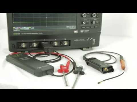
Part 2, this time looking at different types of active oscillocope probes.
Single ended active FET probes, differential active FET probes, current clamp probes, high voltage differential probes, positional current probes, and EMC magnetic and electric field probes.

Buy anything through that link and Dave gets a commission at no cost to you.

Donate With Bitcoin & Other Crypto Currencies!

Рекомендации по теме
Комментарии
Автор

If you want one of those CP2100B 2MHz active probes, use the coupon code "ActiveProbe" in my store for 15%

EEVblog
Автор

The restive transmission line probe is my favorite way to make a built in high speed test point. Because of cell-phones there are some absolutely TINY coax connectors. Many are less than 2.5mm on a side. Add a series resistor and you've got a GHz bandwidth test point for 30-60 cents in < 10mm^2 that securely hooks to the scope with a $5-10 of coax adapters. Easy to AC couple the test point as well, just "tent" a resistor and a cap in series.

martylawson
Автор

The Siglent scopes allow you to set a custom ratio for the probe, such as a 21x if wanted, I did it today on the new SDS1104X-U which I am doing a review video on.

TheDefpom
Автор

I’d love to see an automated test rig where that positional current probe is mounted on an automated XY stage and is scanned across an entire PCB to generate an image of where current is flowing.

robertsundling
Автор

This really opened my eyes to the whole new worlds of higher end probes. I never realized there were so many types of them, and the I-Prober is indeed interesting to see in action.

KeritechElectronics
Автор

some great info in these 2 vids... thanks Dave.. good job as usual!
nice to see im not the only one who pulls out the magnifying glass with SMD stuff!... i need specsavers!

WacKEDmaN
Автор

Certainly good coverage, in fact I have basically all such probes on hand except very high bandwidth FET active type. But also have a isolated HV Probe, with >3KV isolation.
Passive probes to 750MHz, Diff probe to 1700V, current probe 600KHz 100A, current probe 100MHz 15A, I-Probe 520, RF probe set, many custom build coax, twisted pair probes, custom 10MHz low capacitance (0.3pF) 100Mohm diff, special USB cal adapter with SMA sample outputs.
Also created a Mains line access box, to all three lines, with current probe loops and voltage probing access, but such that user is fully guarded from accidental contact with mains, even in case of access to miswired, swapped around lines setup.
I would not want to be without much of such equipment.

helmuthschultes
Автор

My DP20003 (5.6KV differential probe) was a real life saver when we were developing some equipment that went up do around 2.3KV. I hated that project, because you always needed to be 100% vigilant or you risked killing yourself or damaging the equipment.

Nik
Автор

What I did miss in this presentation is the isolated probe Tek developed for high common mode signals (IsoVu). It allows small signal measurement in the presence of high amplitude common mode with impressive CMRR @ 100MHz. This is due to all optical path between the measuring head and base unit. I had the chance to work with both generations and the level of common mode noise immunity and low ground current coupling is impressive. You do have to sell an arm and a leg to get one as they are priced in the range of top oscilloscopes.

pipbogdan
Автор

Nice explanation dave I appreciate your work i've been following your videos for over a year I learned alot from you keep up the great work 👦

mohbit
Автор

The oddest probe i have seen was someone stuck a little 0805 photodiode stuck on the end of a coax with a BNC
it was used for measuring PWM LED strips by someone else who shared the lab
it was nifty at times but obviously its for relative measurements and the signal level was really rather low

OneBiOzZ
Автор

I've made a couple of current sense probes for indication using old VCR head-drum heads or audio erase heads, may not be as fancy as the AIM but are a hell of alot cheaper, have made some probes using infrared LEDs just to see signals from IR remotes, was also hoping to see the large high voltage probes used for CRT testing.

imranahmad
Автор

Normal people: RTX 3080 Max-Q Review
Me: Active Oscilloscope Probes Review

danielhe
Автор

Has anyone done a teardown of one of these expensive active probes? Are they just some off-the-shelf opamps or is there some real unobtanium inside?

kornielsen
Автор

Dave, I'm an electrical engineering college student, and I have been using an ampclamp that was originally intended to be connected to a multimeter. I found it in the trash bin at work. They were just getting rid of it because they got a bunch of new multimeters for our field battery technicians and the new meters all have amplamps built in. It would be really interesting to see how an ampclamp that was designed to connect to a multimeter compares to an ampclamp that is actually for an O-scope. I have been curious about this but have no way to compare myself as I cant afford a CP2100B

michaelsdailylife
Автор

Excellent part two, very useful.
Thanks for sharing.

bostedtap
Автор

Just put capton tape on the mains plug ground pin like electroBOOM does! No need of deferential probe... ;)

nikiamz
Автор

Differential probe divide by ten/hundred, not multiply, right ? 2:35

thomasw
Автор

"HVP70 70MHz Differential Probe
"

Out of stock.

Just like the uCurrent Gold, still out of stock.

mfx
Автор

Curious if you considered the type of your resistor for the 1k DIY probe. My reason is because ages ago I read somewhere that low ohms resistors appeared as inductive, while high ohmic resistors appeared as capacitors, both of course in series or in parallel with the ideal resistor. That was when the (through hole ) resistors were of the Allen-Bradley type -- element buried at the center of "hot molded" mass insulation. Going further, Philips and probably others introduced the type that had a resistive film on top of a ceramic cylinder and overall "paint" on top. That structure reduced the thermal resistance, so higher power dissipation rating in the same size resulted. But there was another benefit -- the resistor element could be grooved to trim the resistance on the production line. Instead of +/- 20% tolerance, the common tolerance then became 5% and even better were available for a minimal price increase. So far so good, BUT the spiral grooving created additional inductance. O.K, all that applied to the through hole type components. I believe present surface mount resistors are likely also trimmed, but depending on the trimming pattern there may be little or no effect to the inductance. So after all this background -- did you use a surface mount or a through hole resistor?

InssiAjaton