filmov
tv
Multiple Servo Control with Potentiometers and Arduino

Показать описание
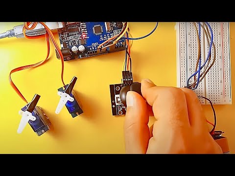
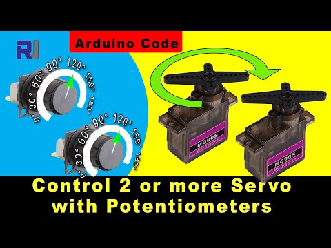
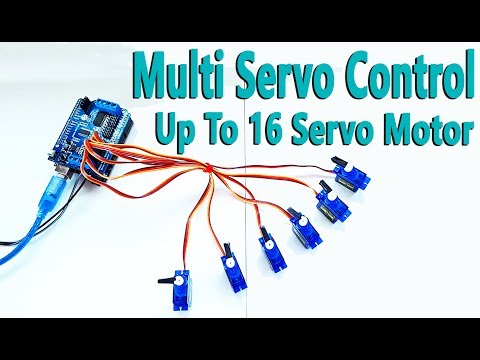
In this tutorial, we will learn how to use multi-servo with potentiometer. We will control 4 pcs servo motor with 4 pcs potentiometer. You can implement your robotic arm projects with reference to this tutorial. Of course we will use external battery / power when doing this.
In the next tutorial, I'll show you how to control servo motor with joystick. Do not forget to subscribe. Thank you for your support. I did not share the code because it is short and it varies according to the number of servo,potentiometer. You can write code by watching the tutorial. This is a better way to learn. I will continue to share long and complex codes.
Required Hardware:
Arduino Board
Servo Motor x4 :
10k Potentiometer x4:
Jumper Wires :
Breadboard:
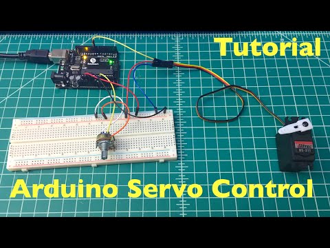
Connections:
The external battery VCC / GND connect to the breadboard.
The Arduino GND connect to the breadboard's GND input
The servo connections we use in this project are as follows;
Orange Input - Signal Input
Red Input - Power Input (VCC)
Brown Input - Ground Input(GND)
The potentiometer connections we use in this project are as follows;
Two other pins are power (VCC) and ground (GND)
Middle pin is signal pin
The Servo1 VCC and GND connect to the breadboard's VCC / GND inputs
The Servo1 Signal connect to the Arduino Digital PWM 3
The Servo2 VCC and GND connect to the breadboard's VCC / GND inputs
The Servo2 Signal connect to the Arduino Digital PWM 5
The Servo3 VCC and GND connect to the breadboard's VCC / GND inputs
The Servo3 Signal connect to the Arduino Digital PWM 6
The Servo4 VCC and GND connect to the breadboard's VCC / GND inputs
The Servo4 Signal connect to the Arduino Digital PWM 9
The Potentiometer's one outer pin connect to the breadboard VCC input
The Potentiometer's other outer pin connect to the breadboard GND input
The Potentiometer's middle pin connect to the Arduino Analog 1-2-3-4 input
Social Media:
In the next tutorial, I'll show you how to control servo motor with joystick. Do not forget to subscribe. Thank you for your support. I did not share the code because it is short and it varies according to the number of servo,potentiometer. You can write code by watching the tutorial. This is a better way to learn. I will continue to share long and complex codes.
Required Hardware:
Arduino Board
Servo Motor x4 :
10k Potentiometer x4:
Jumper Wires :
Breadboard:
Connections:
The external battery VCC / GND connect to the breadboard.
The Arduino GND connect to the breadboard's GND input
The servo connections we use in this project are as follows;
Orange Input - Signal Input
Red Input - Power Input (VCC)
Brown Input - Ground Input(GND)
The potentiometer connections we use in this project are as follows;
Two other pins are power (VCC) and ground (GND)
Middle pin is signal pin
The Servo1 VCC and GND connect to the breadboard's VCC / GND inputs
The Servo1 Signal connect to the Arduino Digital PWM 3
The Servo2 VCC and GND connect to the breadboard's VCC / GND inputs
The Servo2 Signal connect to the Arduino Digital PWM 5
The Servo3 VCC and GND connect to the breadboard's VCC / GND inputs
The Servo3 Signal connect to the Arduino Digital PWM 6
The Servo4 VCC and GND connect to the breadboard's VCC / GND inputs
The Servo4 Signal connect to the Arduino Digital PWM 9
The Potentiometer's one outer pin connect to the breadboard VCC input
The Potentiometer's other outer pin connect to the breadboard GND input
The Potentiometer's middle pin connect to the Arduino Analog 1-2-3-4 input
Social Media:
 0:07:59
Multiple Servo Control with Potentiometers and Arduino
 0:14:39
How to control multiple Servo motors using one potentiometer with Arduino
 0:12:54
Lesson 92: Controlling Multiple servo each with potentiometer| Arduino Step By Step Course
 0:06:08
How to control servo motor with arduino - servo motor control with potentiometer
 0:06:40
Multiple Servo Control with Arduino Uno R3
 0:02:18
Arduino Tutorial Multiple Servo Control with a Potentiometer Arduino Projects
 0:05:37
How to control multiple servo motors with potentiometer using arduino uno.
 0:07:23
Multiple servo motor control by potentiometer using Arduino
 0:00:16
Arduino - Servo motor controlled by potentiometer
 0:04:10
Servo Motor Control with Potentiometer : Tutorial 64
 0:05:53
Realtime Servo Motor Control With Potentiometers
 0:05:36
Multiple Servo Motor Control with Joystick and Arduino
 0:07:57
Arduino Tutorial: Servo Potentiometer Control - Beginner Project
 0:18:49
Control More than one servo using ESP32 with library - Robojax
 0:25:03
Controlling Servo Using Pot and Controlling Multiple Servos
 0:02:37
Control servo motors with a joystick (Thumbstick) | Mert Arduino
 0:12:36
How to control 2 Servo or more with Potentiometers using Arduino - Robojax
 0:00:29
Arduino Servo Motor control using a Potentiometer
 0:01:10
Multi Turn Potentiometer to Postion Control Servo
 0:00:23
multiple servo control using potentiometer and button ⚙️🎛️🔘
 0:04:06
How to Control Servo From Potentiometer and Arduino uno(Creative Electronics)
 0:04:34
How to Control Servo Motor Up To 16 with Arduino Uno R3
 0:05:52
Servo Motor Control with Potentiometer
 0:06:21
DIY Arduino Robot Arm Kit | Control with Potentiometer | 4 DOF | Mert Arduino
Комментарии