filmov
tv
Simple Universal RF Amplifier PCB Design - From Schematic to Measurements

Показать описание
Universal RF amplifier Design - From Schematic to Measurements
Get my free Electronics Product Development Checklist
Check out my courses
In this video, I'm going to show you a very simple way to design a universal RF amplifier. We'll go over component selection, schematic design, pcb design / layout and measurements. We'll also look at the impact of ferrite beads versus resistors in the biasing circuit and the impact of capacitors on the analog performance.
0:00 introduction
0:14 What amplifiers are we talking about
0:47 The selected amplifiers
1:20 Application diagrams
2:00 Single stage amplifier schematics
3:42 Single stage amplifier layout
5:13 Single stage amplifier measurement options
5:54 Measurement setups
8:01 Single stage amplifier measurement results
10:05 Dual stage amplifier schematics
10:51 Dual stage amplifier layout
11:16 Dual stage amplifier measurement options
11:43 Dual stage amplifier measurement results
12:23 Bias current checks
12:54 Good bye and hope you liked it
 0:13:13
Simple Universal RF Amplifier PCB Design - From Schematic to Measurements
 0:00:31
433Mhz 1CH RF mini relay module and control connection | Remote controll
 0:00:36
RF splitter and RF combiner inside the electronic circuit board
 0:00:45
FM Receiver Circuit #electronics #electricalengineering #altium #kicad
 0:06:14
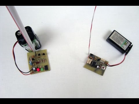
How To Make Simple RF Remote Control One Channel Transmitter and Receiver
 0:07:46
make a simple AM radio , receives all international radio stations
 0:00:30
How To Make Remote Control Tester Using Ir Receiver And Buzzer
 0:06:13
How to Make # IR 4 Channel Remote Control System for your Room Appliances (Very Easiest Way)
 0:01:12
Simple RF Receiver / Transmitter Pair (27 MHz)
 0:08:27
How to make Universal Remote Controller for all Devices
 0:02:12
Using Magic Powers to mess with loud neighbors
 0:00:17
Class D Amplifier
 0:05:47
Build your Own FM Radio with Just a Few Supplies! , utsource
 0:00:23
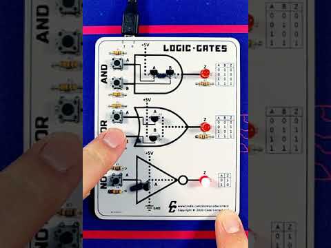
Logic Gates Learning Kit #2 - Transistor Demo
 0:01:00
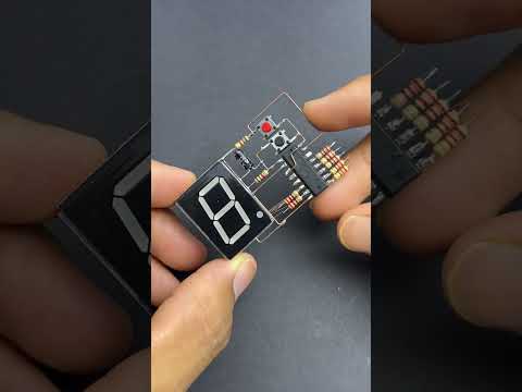
How to make a LED digital counter using 7- Segment Display
 0:01:00
How To Make Remote Control Tester Using IR Receiver and BC557 Transistor
 0:03:37
How to use: 1 Channel DC12V Remote Control Switch with 2 button remote control
 0:05:10
A genius idea that will not come to your mind Say goodbye to remote control batteries
 0:01:24
PCB design:31 - Build this universally popular Audio Amplifier circuit with the PCB design for you
 0:06:51
How to make Wireless Control at Your Fingertips: DIY IR Remote Switch
 0:05:50
Simple Class AB Hifi Audio Power Amplifier | An Audiophile | LCSC Electronics | Easy EDA Parts Store
 0:06:49
Simple wireless Remote control switch using TSOP 1738, IR Receiver Remote control
 0:00:23
3D hologram fan portrait solution. Who wanna date this holographic sexy lady #3dhologramfan
 0:06:27
how to make universal remote control at your home
Комментарии