filmov
tv
What is a Potential Divider or Voltage Divider Circuit

Показать описание
The potential divider or voltage divider is a very straightforward but very useful circuit. As a result the potential divider is found in a large number of electronic circuits.
It is very useful to see what this circuit is and how it works.
As the name implies the potential divider or voltage divider divides the potential or voltage at the input to give a lower output voltage. It divides it down according to the value of the resistors.
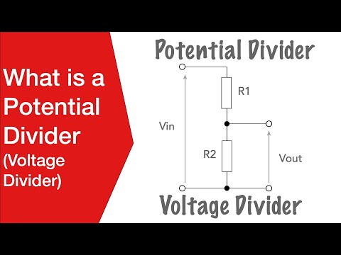
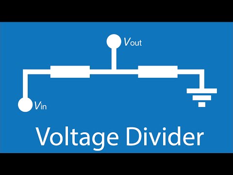
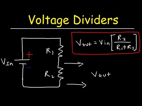
In its simplest form the potential divider consists of two resistors in series. As the same current flows through both resistors the voltage drop across them is in the same ratio as the value of each resistor.
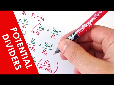
This means the output voltage can be calculated from the formula Vout = Vin (R2 / R1 + R2). The output voltage is the value of bottom resistor in the circuit diagram divided by the total resistance of the chain times the input voltage.
In this way it divides the input voltage down to a lower value.
For the equation to hold true, the load resistance must be sufficiently high for it to be ignored, otherwise it must be included as a resistance in parallel with R2.
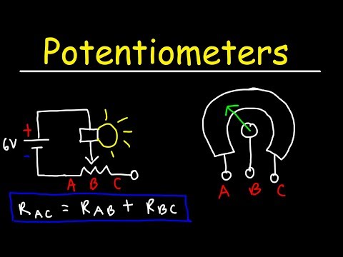
The circuit can also be used with a component like a light dependent resistor so that any resistance variations caused by light changes are converted to a varying voltage. It is found that if the LDR is placed in the lower section of the chain, then the voltage across it will fall with increasing light levels as the resistance of an LDR falls when the light increases.
The calculations for the voltages for the potential divider when light is shining on the LDR:
Vout = 10 x 5 / (5 + 10) = 10 x 5 /15 = 3.3333 V
The calculation for the output voltage of the potential divider when the LDR is in dark:
Vout = 10 x 200 / (200+10) = 10 x 200 / 210 = 9.5238V
If the LDR is placed in the top element of the potential divider and the 10k resistor is in the bottom position.
Then the light voltage will be:
Vout = 10 x 5 / (5 + 10) = 6.6V
and the dark voltage will be 10 x 10 / (200 + 10) = 0.476V
For more information check out our web page:
And please don't forget to "like" the video
It is very useful to see what this circuit is and how it works.
As the name implies the potential divider or voltage divider divides the potential or voltage at the input to give a lower output voltage. It divides it down according to the value of the resistors.
In its simplest form the potential divider consists of two resistors in series. As the same current flows through both resistors the voltage drop across them is in the same ratio as the value of each resistor.
This means the output voltage can be calculated from the formula Vout = Vin (R2 / R1 + R2). The output voltage is the value of bottom resistor in the circuit diagram divided by the total resistance of the chain times the input voltage.
In this way it divides the input voltage down to a lower value.
For the equation to hold true, the load resistance must be sufficiently high for it to be ignored, otherwise it must be included as a resistance in parallel with R2.
The circuit can also be used with a component like a light dependent resistor so that any resistance variations caused by light changes are converted to a varying voltage. It is found that if the LDR is placed in the lower section of the chain, then the voltage across it will fall with increasing light levels as the resistance of an LDR falls when the light increases.
The calculations for the voltages for the potential divider when light is shining on the LDR:
Vout = 10 x 5 / (5 + 10) = 10 x 5 /15 = 3.3333 V
The calculation for the output voltage of the potential divider when the LDR is in dark:
Vout = 10 x 200 / (200+10) = 10 x 200 / 210 = 9.5238V
If the LDR is placed in the top element of the potential divider and the 10k resistor is in the bottom position.
Then the light voltage will be:
Vout = 10 x 5 / (5 + 10) = 6.6V
and the dark voltage will be 10 x 10 / (200 + 10) = 0.476V
For more information check out our web page:
And please don't forget to "like" the video
 0:03:12
What is a Potential Divider or Voltage Divider Circuit
 0:04:42
Potential Divider Circuits - A Level Physics
 0:03:04
Potential Dividers - Physics Revision
 0:05:56
Voltage Dividers - Electronics Basics 12
 0:12:58
Series & Parallel - Potential Divider Circuits - GCSE & A-level Physics
 0:06:30
Potential Dividers - IB Physics
 0:02:46
A level Physics - The Potential Divider
 0:06:15
Voltage Divider Explained | Animated Deep Dive
 0:00:58
2 1k Resistors Voltage Dividers For Half Of 10V #short #shorts #electronics
 0:06:39
Voltage divider | Circuit analysis | Electrical engineering | Khan Academy
 0:25:08
Voltage Divider Circuit Explained!
 0:17:54
A Level Physics Revision: All of Potential Dividers (in 17 minutes)
 0:18:54
Voltage Dividers
 0:00:58
What is a Potential Divider or Voltage Divider Circuit #potentialdivider #resistors #circuitdesign
 0:01:43
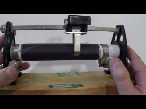
How to connect a rheostat as a potential divider
 0:06:56
Potential dividers
 0:11:00
10.3a Potential Dividers and Ratios | AS DC Circuits | Cambridge A Level Physics
 0:25:21
EEVblog 1399 - Electronics Fundamentals: Voltage Dividers
 0:00:52
Understand a POTENTIAL DIVIDER in seconds #shorts #thecircuithelper
 0:04:27
Potential dividers, what they are and how they work: fizzics.org
 0:04:35
Potential Divider 1
 0:11:11
Potentiometers - Basic Introduction
 0:05:18
How Voltage Dividers Work | AddOhms #13
 0:03:53
Voltage divider tutorial
Комментарии