filmov
tv
DIY: BMW Throttle Position Sensor Testing
Показать описание
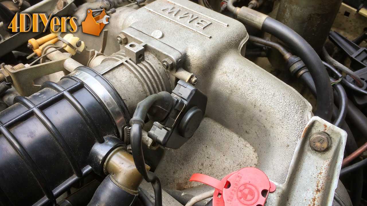
Video tutorial on how to test/troubleshoot and setup the throttle position sensor on a BMW. A faulty throttle position sensor in known to cause poor fuel economy, loss of power, erratic idling, high idle, and increased emissions. This does apply to the older model/style throttle position sensors, the newer models use a potentiometer. If you are removing the sensor, I would also recommend changing the two phillips screws as well because they can be easier to strip as compared to a hex head bolt or allen head bolt. This particular tutorial was done on a 1984 BMW 733i equipped with an M30.
Tools/Supplies Needed:
-multimeter
-phillips screwdriver
-razor knife
-standard/flat screwdriver
Procedure:
-first step is the ensure the throttle position sensor is step up correctly
-with the throttle plate fully closed, open the throttle very slightly and you should be able to hear an audible "click"
-if not the sensor is either broken or not adjusted correctly
-with the throttle plate fully closed, loosen the two phillips screws and rotate the sensor all the way clockwise until you feel it stop
-do not go too far so it opens up the throttle plate
-tighten down the screws
-now retest to see if it has an audible "click", if not the switch is broken
-now testing with the multimeter, remove the wiring harness plug
-on the side of the throttle position sensor, there will be numbers
-3 (wide open throttle), 18 (input single), 2 (idle)
-using the multimeter on the ohms setting, we will be testing each plug to ensure it is working correctly
-with the throttle close, there should be continuity between pinouts 2 and 18, and an open circuit between pinouts 3 and 18
-with the throttle increased slightly, there should be an open circuit between pinouts 2 and 18, and an open circuit between pinouts 3 and 18
-with the throttle fully opened, there should be an open circuit between pinouts 2 and 18, and continuity between pinouts 3 and 18
-if the test fails, the sensor does need to be replaced
-the sensor can be opened up, although it is somewhat difficult
-using a razor knife, cut around the seam to break the glue
-then using a small standard screwdriver, slowly pry away the case
-once open, you can spray the microswitch with contact cleaner or clean the wide open throttle contacts (this is a temporary fix, I would recommend buying a new replacement sensor)
Thank you to all those who watch my videos and support my content. Don't forget to subscribe to my channel for future tutorial videos and like my video if you found it helpful. New videos are always being uploaded every week!
© 4DIYers 2013
All Rights Reserved
No part of this video or any of its contents may be reproduced, copied, modified or adapted, without the prior written consent of the author.
 0:08:19
DIY: BMW Throttle Position Sensor Testing
 0:08:22
BMW e46 M3 Throttle position sensor TPS replacement guide
 0:00:17
Throttle Position Sensor Resistance - TPS BMW E36 M50 320i
 0:01:34
How To Reset BMW E46/E39 Throttle Position
 0:01:35
BMW Throttle Adaptations in 1 min
 0:05:03
BMW R1100, R1150, R850 Throttle Body Sync DIY How to
 0:03:10
How to Stop Car Hesitation (Throttle Position Sensor)
 0:10:55
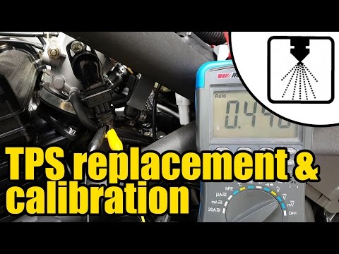
How to install & calibrate a new Throttle Position Sensor (TPS) #1208
 0:09:44
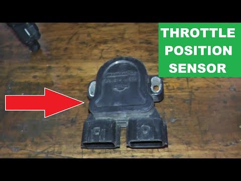
How To Replace and Adjust the Throttle Position Sensor
 0:03:37
BMW E46 M3 Throttle Position Sensor Replacement DIY (2001-2006 BMW S54 Engine)
 0:02:06
Bad Throttle Position Sensor - Symptoms Explained | Signs of failing throttle position sensor (TPS)
 0:03:57
6 Faulty Throttle Position Sensor Symptoms & Replacement Cost
 0:01:39
Throttle Position Sensor (TPS) replacing, BMW E36M43
 0:01:57
How To Reset a Throttle Position Sensor
 0:06:41
How it Works - Electronic Throttle: Motorvate's DIY Garage Ep.30
 0:02:47
What Happens If The Throttle Position Sensor Of Your BMW Goes Bad From Experts in Hellertown
 0:00:59
A throttle position sensor for your E30?!
 0:04:22
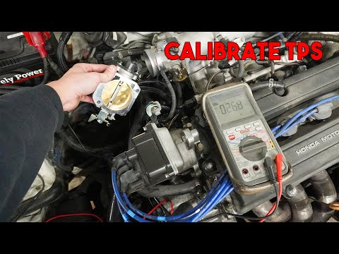
How to Calibrate Throttle Position Sensor Using a Multimeter (Set TPS)
 0:06:56
Throttle Position Sensor adjusting the easy way!
 0:13:13
Throttle Position Sensor Testing On BMW R Series Motorcycles
 0:00:59
How to set your volt meter for adjusting a TPS (Throttle Position Sensor)
 0:03:32
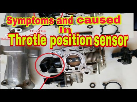
Throtle position sensor faults and symptoms / caused and effect of bad Throtle position sensor andam
 0:03:49
What to do after replacing throttle position sensor
 0:00:26
Throttle Position Sensor Replacement // Bad Throttle Position Sensor//P2135 Throttle Position Sensor
Комментарии