filmov
tv
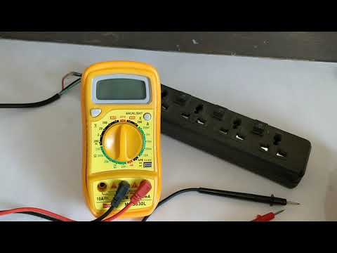
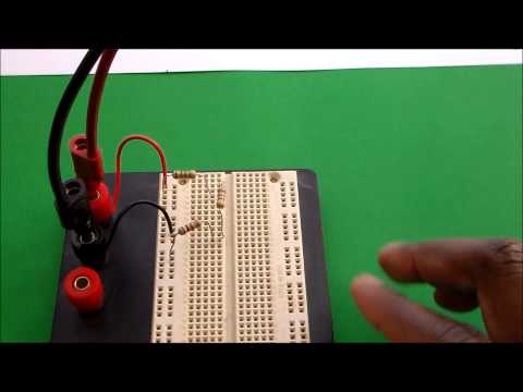
How to Measure DC Voltage and Current in a Series Resistor Circuit.

Показать описание
In the video I demonstrate how to measure voltage and current in a resistor circuit where the resistors are in series. This is a very common activity performed in a Electricity and Magnetism Physics Lab.
 0:01:49
How to measure DC Current with a multimeter?
 0:00:25
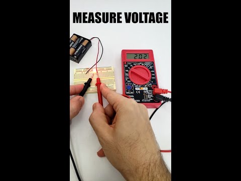
Measuring DC Voltage with Digital Multimeter
 0:08:08
How to Use a Multimeter for Beginners - How to Measure Voltage, Resistance, Continuity and Amps
 0:02:28
How to Measure DC Voltage with Multimeter
 0:00:18
Measuring AC Voltage with a Digital Multimeter
 0:00:47
How to Measure Voltage with a Multimeter
 0:00:20
How to Measure DC Voltage with KAIWEETS HT118A Multimeter?
 0:02:13
Siglent Oscilloscope DC voltage measurement Procedure
 0:37:29
Measure DC Voltage and Current with Arduino
 0:00:48
Grounding Your Body And How To Measure // DC Voltage
 0:06:00
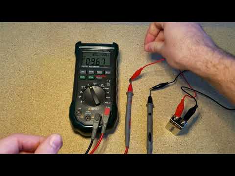
How to measure DC voltage with a DMM / Digital Multimeter
 0:08:33
How to Measure DC Voltage with a Multimeter
 0:01:56
Measuring Voltage with an Oscilloscope - The Keysight 2-Minute Guru (s2e5)
 0:11:44
What is a SHUNT? (Used to measure Current) + How to make a DIY version
 0:01:36
How To Use The Basic Meter Function (Types of Voltage Selection)
 0:04:36
THE BEST Multimeter tutorial (HD)
 0:01:53
DT266 Clamp Meter How to measure DC Voltage | Multimeter
 0:00:14
Measuring voltage the right way #electronics #electricity #electrician #voltage #outlet
 0:01:27
How to Measure AC Voltage with Multimeter
 0:09:47
How to Measure DC Voltage and Current in a Series Resistor Circuit.
 0:11:24
Can my $15 DIY AC/DC Current Clamp keep up with a commercial one? || DIY or Buy
 0:09:52
How to Use a Multimeter & Electricity Basics | Repair and Replace
 0:00:18
How to Measure AC Voltage with KAIWEETS HT118A Multimeter?
 0:04:32
Measure Voltage & Current at the same time with a DMM
Комментарии