filmov
tv
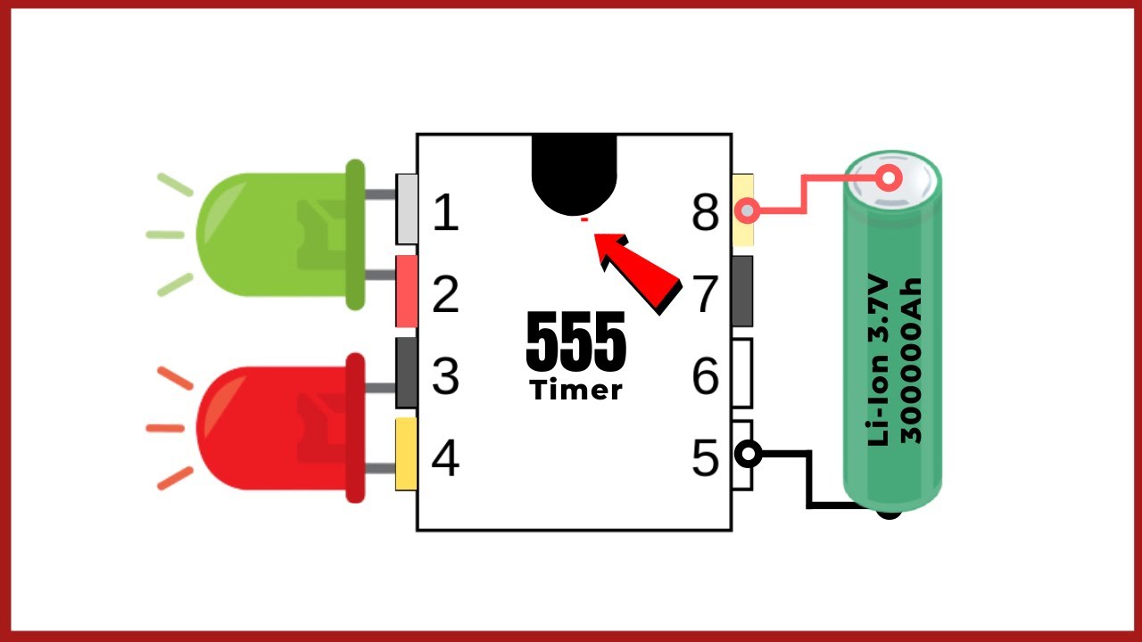
LED Flasher Circuit
Показать описание
In this video, I will show you How To Make Dual LED Flasher Circuit?
**Note: Some People copy my content as well as the thumbnail. I have no issues with content as long they make it themselves. But for the thumbnail, It belongs to respective owners (Some also created by myself). If you get a copyright strike without any notice by copying my thumbnail then it is not my fault. Happy Creating :)
Needed Components Online Link-
Amazon US:
Amazon India:
I hope this video was Useful and you liked it if you did press the thumbs up button.
Cheers!
Creative Creator
:)
**Note: Use Heat shrink tube for making all connections Secure.
Follow Me On Social Sites
------------------------------------------------------
Thanks For Watching
✅LIKE ✅SHARE ✅ COMMENTS✅ SUBSCRIBE
#DIY #LED #flasher
 0:00:49
Simple LED Blink Circuit using BC547 Transistor: Breadboard Project
 0:07:50
LED Flasher Circuit
 0:02:11
LED Flasher Circuit Using BC547 | The Simplest
 0:00:17
Blinking LED Circuit 12v| Strobe Light| Strobe Light Effect| Strobe Light LED| Strobe Light Circuit|
 0:06:49
How a 2 transistor LED flasher circuit oscillator works | Easy simple explanation
 0:07:15
LED Flasher Circuit
 0:04:05
Simple LED Flasher Circuit
 0:00:16
Simple 220V LED Flasher Circuit | DIY Electronics Project
 0:00:18
12v dc LED bulb kaise banaye | 12v LED bulb kaise banaye #short #shorts
 0:02:28
Single Transistor LED Flasher Circuit
 0:06:12
Police Lights Themed LED Flasher Circuit | 555 Timer Project #13
 0:00:58
Simple led flasher using bc547
 0:03:55
Single LED Flasher Circuit using a Breadboard
 0:00:59
LED Flasher Using BC547
 0:00:31
NE555 Projects | NE555 LED Flasher | Circle LED Light | Round LED Light | Running Light Effect |
 0:00:43
Simple and Powerful LED Flasher Circuit Using BC547 #shorts #zaferyildiz #short #electronics #viral
 0:05:59
FLIP FLOP LED Flasher Circuit Using Transistor BC547 (Breadboard Tutorial)
 0:02:20
SIMPLE FLIP FLOP LED Flasher Circuit Using Transistor BC547
 0:03:55
DIY Super Fast Flasher Circuit | LED Flasher | Electronics Projects
 0:05:03
led flasher circuit with optocoupler
 0:00:37
Simple and powerful LED flasher circuit diagram BC547 #shorts #pbexperiment
 0:00:57
Superb LED Flasher Circuit Using Optocoupler #shorts #zaferyildiz #short #electronics #viral
 0:00:31
Single transistor simple LED blinking circuit #shorts #diy #shortfeed
 0:00:53
How to make a LED flasher using relay
Комментарии