filmov
tv
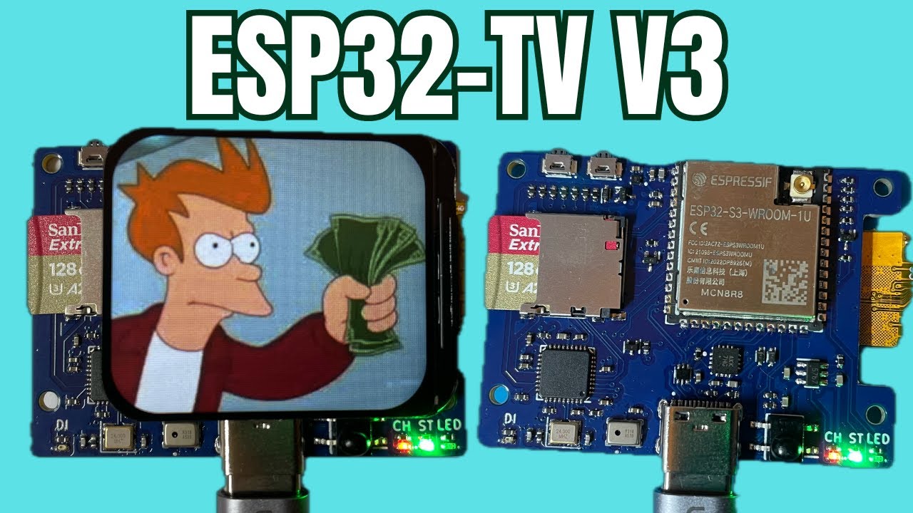
ESP32-TV Version 3 - Is it done?
Показать описание
The good news is - they work! Everything is behaving as expected and the new stuff on the board is also working.
But I'm still not completely satisfied. I think there's room for version 4 - what do you think?
0:00 It works!
2:50 We have a microphone!
4:46 SD Card Performance
9:24 I'm still not satisified
10:13 Some Unexpected Inspiration
13:23 Bonus Content!
These are both a work in progress - Use at your own risk!
---
And if you're shopping on AliExpress or Amazon then if you click on these links I will get a little bit of affiliate money:
 0:13:51
ESP32-TV Version 3 - Is it done?
 0:09:26
Arduino To ESP32: How to Get Started!
 0:03:43
Broadcasting Analog TV on an ESP8266!
 0:01:01
ESP32 Explained In 1 Minute! #IoT #robonyx #electronics
 0:00:18
M5StickC Plus - ESP32 Marauder
 0:00:26
ESP8266 broadcasting analog TV on channel number 3
 0:13:15
Finally, ESP32 board with an AMOLED display .LilyGO T-display S3 AMOLED
 0:00:12
Spotpear ESP32-C3 Development Board with 0.42' LCD Display for Arduino Micropython WiFi Bluetoo...
 0:00:17
Super Cool Mini Wireless Monitor #shorts
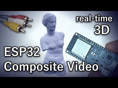 0:05:56
ESP32 Composite Video
 0:00:22
CONSTRUYO mi propio TV BOX con AndroidTV 📺
 0:08:50
12 Mind-Blowing ESP32 Projects to try in 2024!
 0:00:24
Flipper Zero Alternative? - m5stickC plus 🤯 #shorts
 0:00:31
Wait what 😱 Flipper Zero 🐬
 0:10:20
STOP Buying ANDROID TV Boxes!
 0:00:15
Vivo v23 pro display without glass || flexible paper display|| edge screen
 0:07:09
ESP32 VGA [Arduino, 3D]
 0:03:56
ESP32-CAM: Unboxing & Setting Up
 0:09:10
Smarter than a Smart TV! (Raspberry Pi Inside)
 0:00:16
THIS device will CHANGE your room! #LaserCube #shorts
 0:00:34
Can The Flipper Zero HACK A TESLA? #shorts
 0:00:15
Amazing PS5 Upgrade (LEDs)
 0:00:14
NEWYES Calculator VS Casio calculator
 0:05:13
Raspberry Pi Pico VS ESP32 S2 speed comparison benchmark using CircuitPython
Комментарии