filmov
tv
Does a DIY Audio Crossover make sense? How passive filters work! || EB#41

Показать описание
Websites which were shown during the video:
In this video we will have a closer look at audio crossovers. That means I will demonstrate why they need to "split" the frequencies of your music signal and what components are capable of accomplishing this job. This way we will learn quite a lot about passive filter in order to answer the question whether it makes sense to replace an existing audio crossover or creating a DIY one. Let's get started!
Thanks to JLCPCB for sponsoring this video
Music:
2011 Lookalike by Bartlebeats
Killing Time, Kevin MacLeod
 0:08:04
Speaker Crossover Explained - Introduction to Parts and Orders
 0:11:49
Does a DIY Audio Crossover make sense? How passive filters work! || EB#41
 0:10:12
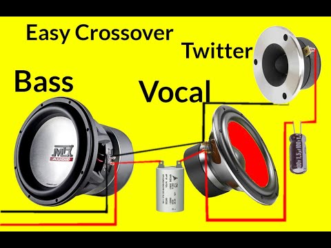
how to make crossover for speaker?
 0:14:49
How to Pick The BEST Drivers For Your DIY Speaker Project
 0:15:20
DIY Reference Quality Speaker Build. How I built these amazing speakers and proper sound comparison!
 0:18:48
Design Crossovers for HiFi speakers using Xsim - Tips and Tricks
 0:06:27
YES! You CAN build $5000 HiFi Speakers for UNDER $500 DIY vs HiFi
 0:09:59
The Best DIY Speakers for Under $300? Crossover Design and Overview
 0:06:42
JL AUDIO SIMILAR SETUP UPGRADED IN THAR AND HONDA CITY @rscarmodifiers
 0:08:02
How To Make Speaker crossover || Capacitor, Resistor, Coil, Lpad Fonction
 0:00:33
Simplest DIY audio crossover to protect your tweeters.
 0:11:13
How To Design A Crossover For A DIY Speaker || Part 1 - Crossover Design Intro
 0:04:01
Tweeters, Woofers, and Subwoofers | What Is A Speaker Crossover?
 0:33:45
How To Design A DIY Crossover Using Free Software | Live Crossover Design
 0:09:59
5 Tools Every Speaker Builder Needs
 0:04:13
How To Pick A Crossover Type | Step 2 | DIY Speaker Building
 0:01:52
Diy Bass Booster Speaker | 3 Way Hi Fi Speaker crossover
 0:15:42
How to Make a Crossover Board from a Schematic / Diagram
 0:06:14
3 Way hifi Speaker crossover
 0:13:35
6-3-All about crossover design_Free software_part3
 0:03:02
How to set Crossovers
 0:10:43
How to Design a Speaker - Epic HiFi Technical Breakdown
 0:22:20
Building EXCEPTIONAL speakers using MODERN TECHNIQUES
 0:06:15
Can a Newbie Build a Speaker Crossover? YES.
Комментарии