Ignition Coil Drivers

preview_player
Показать описание
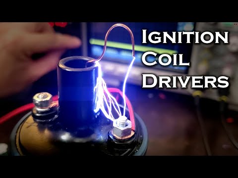
In this video I show the differences between an ignition coil (pulse transformer) and other types of transformers, and a few different ways to drive them to get a high voltage output.

An ignition coil is an induction coil that has a relatively high primary inductance, but low turns ratio. It generates high voltage by building up a large magnetic field in its primary, and then suddenly collapsing it when current is shut off. The sudden collapse causes a voltage spike in the primary, which is stepped up even further in the secondary coil. These devices can easily produce 30,000 - 40,000 volts with a 12 volt input, and a modest turns ratio of between 15-20.

In the video i show how to drive one with a relay, single MOSFET, inductively coupled MOSFET half bridge, and a 600V IGBT, which was by far the most powerful and effective circuit.

Some important components:
-555 Timer
-LM7805 Linear Regulator
-IRF640 200V / 18A MOSFET
-12TQ200 200V / 15A Diode
-MUR120G 200V / 1A Diode
-STGP20H60DF 600V / 20A IGBT (Best results by far)
-1N4148 Diodes for duty cycle adjustment

Ignition coil used:

Music:
Serge Pavkin - Modern Technology
Kevin MacLeod - George Street Shuffle
Heatley Bros. - Otherworld
Serge Pavkin - Intergalactic
Рекомендации по теме
Комментарии
Автор

Amazing how well the old set of mechanical points and condenser distributor worked, and rotor & cap delivered spark to each plug at the right timing. Much improved by early electronic ignition control, and powerful magnetos.

victorbruce
Автор

Fascinating! I have no real use for any of that, and yet I feel a strong urge to go buy an ignition coil.

hopelessnerd
Автор

A video that doesn't skimp on the necessary details but also doesn't overburden the viewer with too much detail or too much math - that is a recipe for a good video.
I have fixed a couple of the electric fence generators which were made too cheaply with crude soldering skills and solder with too much lead (cheap Chinese solder with a lopsided ratio of 40/60 instead of 60/40). There are many schematics on the net for this, but they basically involve charging a high-voltage capacitor of 10-30uF to around 200 something volts and discharging it through an SCR into the car ignition coil primary. This produces a powerful and painful high-voltage spark (No, I haven't tested it on myself, thank you very much!). The circuitry is crude and simple, it is surprisingly efficient at 12V (uses about 200mA, to step it up to 200+ volts), but by my calculations it is still using about 3 times more energy than it should (the efficiency maybe around 30%). It is using a standard iron core transformer with a 555 driver and a MOSFET and then going through a very high resistance to charge the main capacitor, which is a waste. I figured I could use a much smaller ferrite core transformer with pulses calculated to charge up the capacitor in one second, without using a resistor, which would greatly increase the efficiency.

edinfific
Автор

Great video man, I really appreciate the fact that you include formulas.

zionfranz
Автор

This is hands down a top notch showing of an arcing circuit. I have so many questions for you that you would probably tell me to take a hike. I tip my hat to you SIR

victoryfirst
Автор

6:02 some O.E.M, ignition systems use a NPN Darlington such as a BU941 or MJ10012, which might take a little more current to drive than a MOSFET, but have a higher voltage rating. Might be more expensive in a TO-3 package than the TO-220 ones you're using, but they have to work all day in all climates located near a hot engine. Thanks for the video.

alexjenner
Автор

One of the best produced e-engineering videos around

fjs
Автор

I am totally amazed at individuals such as yourself that have the ability to understand the principles of electrical current. Just fantastic !!!

georgezadanski
Автор

This was a super cool walk through the world of inductance, coils, resonance, resistance and all the other components at play in the relationship to this spark energy system! 2 learnings in as many days....Electroboom just released a new video with a very good in-depth about capacitive coupling with wires. I hope to see more of these deep dives into common systems . Nothing better than learning something new about something you thought you about already.A walk through how Tesla bifilar coils and circuit to demonstrate its purpose would be so much for the great journey!

Buzzhumma
Автор

I've done some sketchy stuff with these ignition coils, in fact I was almost killed by one a few decades ago lol. My 15 yr old genius mind hooked one of these up directly to a wall outlet, I had to dunk it in motor oil to prevent arcing and cool it since I was running gobs of current through it lol. I was fooling around with the 2" arcs it made, which were hot enough to melt steel wire, when it shorted out to the metal table I was working on and holding on to with my right hand (genius move, I know, I was staggeringly intelligent in my youth🤣) and the electrode in my left hand, my right hand clamped down on the table so hard I couldn't pull away and my left hand was squeezing the wire, I was stuck on it for about 5 seconds before I could get my legs to start kicking and push myself away. I pulled so hard I ripped the transformer out of the jar of oil and sprayed used motor oil all over myself and my shop, but more importantly ripped the outlet out of the wall and saved myself from an awful death. My entire body was cramped for days and I'm not sure how it didn't stop my heart, I think it must have been making 20k-30k Volts based on the length of the arcs it made, which were very similar to a flyback transformer arc but noticeably hotter. Moral of the story, don't hook these up to unlimited current sources, you might die...

TheExplosiveGuy
Автор

RIP all you neighbors enjoying their nightly AM programming

snowdaysrule
Автор

In your attempt to drive at resonance (8:07), the parasitic drain to source diodes were probably the main problem. Many years ago I worked with high voltage supplies that used a near resonant H bridge driver to deliver a little over 1 Amp at up to 145KV. The H bridge used SCRs, and the transformer primary with a series cap was placed across it. As you approach resonance, the series tank impedance goes lower, resulting in more output power. There was no second chance if you made the wrong mistake while working on it... ⚡

Motor_Cackle
Автор

Ignition transformers are great, one time I had 2 of them in series being driven by the output of a MOT, it created massive 6" plasma arcs between the output terminals.

Leviathans
Автор

Many years ago on my 67 Mustang, I added an MSD ignition unit and an upgraded Accel coil, That combo could make some strong and long sparks!

stevem
Автор

I had some great fun many years ago, I was using a version of a capacitor discharge ignition (CDI) that were popular electronics kits many years ago. I had the same issue as you as in the centre insulator kept breaking down and killing all the fun. Luckily there was a few very rare coils with ceramic insulators on top at the local tip.
These did not punch through, however the spark would still make it directly between the output terminals and not my target terminals. I fixed that by extending the centre insulator with some plastic pipe.
In the end, I had a 500V cap dumping into two coils in series, anti-phase, one producing a positive pulse, whilst the other did a negative pulse. The best spark I was achieving was 7cm. However my inverter took about 20 seconds to recharge the dump cap, so it was a long way from a continuous arc. The discharge was by a heavy duty 'starter' press button, so no diodes or caps were used to limit the voltages.

Unfortunately that was one of the things that didn't make it when my parents moved houses.

paulstubbs
Автор

One little addition to the ignition coil construction description: There is also a few pairs of core material sheets curved around the winding pack. That serves to provide a return path for the magnetic field, reducing the air gap in the loop. As a side effect, it may also shield against some of the noise radiation. On the old automotive implementation, there is a small, maybe 0.5 ohm series resistor to limit the primary current. The capacitor was usually across the breaking contact, with an explained purpose of reducing the sparking of the contact. However, the contact spark erosion stiil was a common trouble issue.

InssiAjaton
Автор

That last frame showing the electric arc burning relentlessly into the insulation reminded me of the 'Id' beast in the last scene from the SF film 'Forbidden Planet'.

Useful video - especially the explainer on IGBT's. My favourite field has always been power electronics, from building an OpAmp driven bank of triacs back in the 70's to power a discotheque sound to light show.

tiggywinkle
Автор

That was kinda fun. 😁
As a motorcycle instructor I've checked back EMF on motorcycle ignition systems a few times.
One I particularly remember is mid 90's Suzuki VS800 (Intruder)
The back EMF maximum was 318V measured with a peak voltage adapter on regular electronic multi meter with input around 13.8v DC (regulated voltage when charging battery)
Output voltage around 45, 000v but had no means of checking max voltage accurately (I'm a motorcycle mechanic not electrical engineer/hobbyist )

crazypj
Автор

Déjà vu ! Many, MANY moons ago, I worked next to the people who actually designed the the circuits to drive ignition coils (and injectors) in electronic engine controls. IIRC, they just used a MOSFET. There was no capacitor across the coil (there WAS in old "point style" ignition systems). The important thing was a zener diode across the driver transistor to protect it from back EMF. The zener voltage had to be high enough (57V?) to allow the primary coil to collapse quickly but not too high to to allow damage to the transistor.

When gasoline engines are running at low RPM (<2000?) there is actually enough "time" to "recharge" the coil and "strike again". At <1000 RPM, it may do this 2-4 times.

As you found out, arcing down the center tower ruins the coil because the leaves a carbon trace. Once that trace is there, it is next to impossible to remove. I had an old car with point ignition that would mis-fire in damp weather. Turned out, it had an invisible, to the naked eye, carbon trace that would conduct when it was damp.

jackpatteeuw
Автор

Wow you are a God. I've played with this stuff my entire life. You just dove into the physics of why these coils don't like AC only true pulsed DC. VERY nice job.

flaplaya