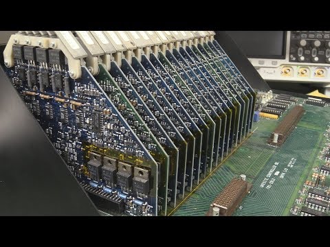
EEVblog #1061 - Data IO Programmer REPAIR - Part 1

preview_player
Показать описание
Repairing the Data IO universal programmer.
Will it be a happy ending?

Support the EEVblog through Patreon!

Stuff I recommend:

Donate With Bitcoin & Other Crypto Currencies!

Рекомендации по теме
Комментарии
Автор

As a noob hobbyist I have no problem following along, you have a great way of explaining things, and you give us a great view of what you're looking at. I really appreciate it, thanks Dave ;)

SuprSi
Автор

Easiest way to debug shorted rails is to stick an amp or two in from an external PSU and use a thermal camera. If it's so dead-shorted that it doesn't heat up, then using a mV meter to home in on it is usually easier than doing resistance measurements as you don't have the contact resistance issue.

mikeselectricstuff
Автор

Data I/O - engineered and built like battleships. My model 29B's (I have 3) just keep working with minimal maintenance over the last 20 years. I bought them used on eBay auctions (the shipping was more than the purchase price for one or two of them). It blows my mind that I am using equipment that I used BITD when I was a young engineer in the early 80's. I repair old arcade PCBs from the 80's and use them to program really old bipolar proms and early eproms.

reasonablebeing
Автор

Nice repair video, well done. But to get things running, the Unisite needs to boot on a master floppy or a MSM module and with all the boards and adapters plugged. Until that, the self-test led will remain on indefinitely... (Also, about the previous video, don't touch the golden pin of the adapter: you could get a "fail" during the self-test just due to that... Use a little isopropyl alcohol to clean it, in case).

etienneguyot
Автор

In the late '80's we used one of those as a large multi-gang programmer/tester. We were in a tightly controlled industry (nuclear power plant instrumentation), and so we developers made "Golden ROMs" that were cloned en masse for production. I believe the unit handled one master EPROM and 32 slave chips. The master had to be checksummed before and after each use. The slave chips were each validated multiple times after programming, over the full rated operational voltage and timing range for the chip.

flymypg
Автор

You could also point a thermal camera at the board while trying to power it up.
That works like a charm for me every time I need to find a component that's shorting a power rail to ground.
It's much faster than dicking around with a multimeter. You can record video with the thermal camera, and check it later, so you can do it quickly, to make sure you don't damage anything else on the board, trying to drive current through it.

gnagyusa
Автор

remove the kernel test jumper look for output.

chevsev
Автор

Awesome Dave! you finally got your hands on an interesting repair, can't wait for the next one

Lordniksidor
Автор

I used one of these a few years ago (also had the smaller 3900), from memory it looks for a terminal at boot/power-on as part of self test (already suggested previous comments I think?) we used a VT340 terminal to operate ours and later moved to using terminal emulation in Windows Hyperterminal as it had the option to emulate the VT340.

blues
Автор

From what I can see in the documentation (and I may be off the mark - I admit), the self test light stays lit until it sees a disk. I'm guessing the test routines are actually part of the OS bootstrap.

FatedSnowfox
Автор

That tantalum cap at 11:00 I spotted because of the colour, it stood out as the bad one to me even before you tested it, it is slightly darker which happens when they get hot from shorting.

TheDefpom
Автор

Self test failure due to modules not being plugged in ?

TheDefpom
Автор

around 10:00 that reminds me of the grid of transistors. Moving around the grid gives different resistances. I didn't see boards like that in the past. neat.

pierQRzt
Автор

OK! I found you! It is the next video, duh!. (I just watched #1060 and I am two years late. Better late than never! If this is the first video you are seeing on this, watch #1060 first. What a gorgeous device.

jlucasound
Автор

So glad you're sharing the repair with us! I was hoping you would after the original video!

BritishAdam
Автор

Hey Dave.
The video is older but:
Will there be part 2?
I would really be interested in whether you can repair the device. Greetings from Germany

The_Watcherk
Автор

Tantalum friends are very common to go happy like that :-D
i'd replace ALL of them without even powerin up :D

xDevscom_EE
Автор

I so love tear-down and repair vids like this! This is a bit outside my skillset I would say, more just find bad e caps with my ESR or completely nuked components, but I certainly hope to be someday.
I look forward to part two!

aanarchyy
Автор

Given you are getting messages from the tty port, I assume the 68k
is resetting and fetching code from those EPROMs. ....but the lack
of further output means it is wedged or in an endless loop with no
messages to say what is wrong. Maybe use a logic analyzer to see the
access to the EPROMs? May get a clue to see if it is stuck or see what
sequence is occurring?

joefenech
Автор

I didn't see the first "Tear Down" video on this one, but would LOVE to see a completed repair on it! I wonder if the problem could be a corrupted "self test file", sort of like having a "IF THIS, THEN statement that isn't completed anymore, and it is still waiting on what "then" is. I enjoy your programs!

waynethompson