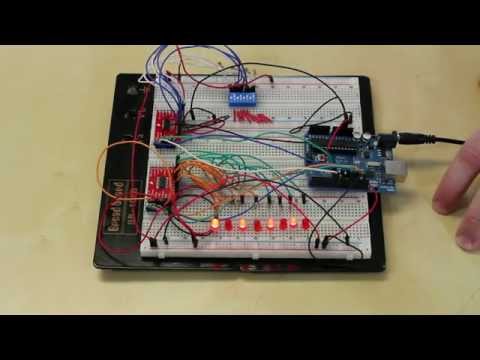
74HC595 Shift Register with 74HC86 XOR Gates

preview_player
Показать описание
The spooky world of the linear feedback shift register.

Рекомендации по теме
Комментарии
Автор

I love the these kinds of videos. They probably have a limited audience but they will keep being educational for as long as Youtube is in business and there will probably be new nerds wanting to learn about this stuff.

dentakuweb
Автор

At it's most basic level this is how data encryption works.

Both parties have extremely long shift registers, and only they know the feedback taps to the xor gates.

When data is transmitted in a binary form (even if it started life as sound) it is passed through the shift register and what comes out the other end is totally encrypted. The data can then be broadcast with confidence that even if it is intercepted, no one else knows the feedback xor feedback taps and the large length of the shift register.

Just have to keep those xor taps and shift register length secret!

nigeljames
Автор

Too much for me to understand fully but guessing kurnaugh mapping patterns might fit into the subject somewhere also a difficult subject to understand.

keithcitizen
Автор

The data sheet for the 74hc595 says its fine to connect SHCP and STCP together. If both clocks are connected together, the shift register will always be one clock pulse ahead of the storage register. You effectively get a 9 bit shift register with bit 0 hidden inside the chip.

gedtoon
Автор

Great video! The applications for this are wonderful for me! Thanks for making this.

SouthShoreSonics
Автор

Thank you. You made it easy to understand what was happening while it was happening.

frankowalker
Автор

I hope you swiped up all the ones that dropped out the end and made a mess on the workshop floor!

Anvilshock
Автор

Great video, not spooky at all. <g>

BryanByTheSea
Автор

I made something like this, out of 4 74hc595shift registers, 2 pairs in series and the 2 series in parallel, in a closed loop with the posibila of adding 1s and 0s but instead of a xor gate chip I used a hex inverter chip to invert the data ST_CP and SH_CP.

SpaceMonkey
Автор

Nice channel, , ,

find so rare video that explains shift register..
Thank you..

thomasalexander
Автор

shift register can be made with only xor gates and some way of extending the signal. And obviously a clock! Such simple circuits! (especially in minecraft where its stupidly easy to add delay)
then you can tack on any kind of extra features that you want. it could even be the heart of a simple calculator or who knows what else you could come up with! And with multiple shift registers in parallel and in series you can generate binary numbers and convert it into decimal or whatever you want.

realflow
Автор

Try hooking two audio-frequency 555 astable circuits up to the inputs of an XOR gate and fiddle with the frequencies. You get some awesome sounds out of it if you tune the two oscillators to different intervals.

matthehat
Автор

// Just one line of code inside the loop:
lfsr = (lfsr >> 1) ^ (-(lfsr & 1u) & xorMask);

// Galois Algorithm - more efficient than Fibonacci

BritishBeachcomber
Автор

Woohoo!!!! Thank You For That Amazing Video!!!! I have been waiting for this video and I'm glad I did, it was absolutely wonderfully weird and extremely in depth, interesting, educational, and entertaining!!!!

Thanks for taking my request for a follow up on Linear Shift Registers!!!! I actually understood what you were doing even with my entry level understanding of electronics and that is what makes you an extremely valuable resource for anyone who wants to know more about everything electronics has to offer!!!!

ZaneDaMagicPufferDragon
Автор

Just ported the code to Arduino and breadboarded it. Refined the algorithm using a table of XOR masks for any shift length. Will publish the code and maybe a video soon.

BritishBeachcomber
Автор

In your opinion what is the best 6 cell 18650 battery bank that doesn't require soldering? Thanks and keep making these awesome videos

nayelelkiki
Автор

Just need an Arduino, LEDs and some C code...
include <stdint.h>
int main(void)
{
   uint16_t start_state = 0xACE1u; /* Any nonzero start state will work. */
   uint16_t lfsr = start_state;
   uint16_t bit; /* Must be 16bit to allow bit<<15 later in the code */
   unsigned period = 0;
   do
   {
       /* taps: 16 14 13 11; feedback polynomial: x^16 + x^14 + x^13 + x^11 + 1 */
       bit  = ((lfsr >> 0) ^ (lfsr >> 2) ^ (lfsr >> 3) ^ (lfsr >> 5) ) & 1;
       lfsr =  (lfsr >> 1) | (bit << 15);
       ++period;
   } while (lfsr != start_state);
   return 0;
}

BritishBeachcomber
Автор

Hi Julian,

Thanks for the channel, I find it quite informative and worth the subscription! :)

I had a thought while watching this video - could one substitute the 16MHz crystal oscillator that is used with an ATMEGA328P (Arduino UNO) with a 555 timer. Thought this could be a very nice video for you to produce as it seems like it is very much up your alley. I know that the limit of a 555 timer is 500kHz, but perhaps some sort of multiplier circuit could be employed?

Does it seem like a worthy/feasible investigation to you?

Thanks,

Dylan

dylanreynolds
Автор

love this stuff - takes me back 30 years or more. Encryption needs randomness...

followthetrawler
Автор

This was/(is) used within the pseudo-random signal generators(=digital white noise). There was even a time where you could buy such a thing already done in a single chip solution where the last stages have been accessible.

tubical
visit shbcf.ru