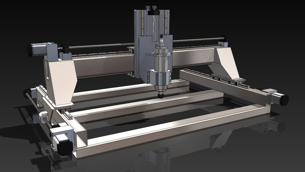
Exploring the Design Changes of my PrintNC CNC Machine

preview_player
Показать описание

#CNCMachine #PrintNC #design #CAD #Zassembly #gantryrisers #weldedgantry #steelwelding #updates #iteration #inaction

If you enjoy my DIY CNC projects, consider supporting the channel on Patreon. Your support helps me create more content and improve the channel. Thank you!
Рекомендации по теме
Комментарии
Автор

As a retired structural engineer, I compliment you on your design changes. I think you made many improvements.

sreed
Автор

Just a Y axis holder redesigned, PrintNC becomes more powerful now. The 2 pieces Y axis
holder can build itself, a must upgrade.

efrencuadro
Автор

hi there, nice mods, how do you plan to square everything after welding? i'm curently building one of those too and had an idea to prevent dirt from going onto the rails and ballscrew with bathroom ventilation pipes, surely not perfect but you can adapt it to your flavor, i can share the fusion file if you want

pholos
Автор

I think you should mount the X axis ballscrew on the backside of the gantry, instead of being above the linear rail.
That has some advantages, one of them is that it stays much more chip free. Also, it let's you upgrade and use stronger Z mounting brackets to the X axis.
I did this on my design.
BTW,
My machine is not a PRINTNC
I like your channel 😁

pmsilvei
Автор

Love the overall improvement on rigidity, dual bearing on each rail, aso.
My concern is about the welded gantry risers. They will most certainly require post machining due to the stress and warp induced by the welding operations.
It would turn the project out of reach of lots of makers imho (plus you'd have to rename it from "PrintNC" to "WeldNC" 🤣)

sergeb
Автор

First of all, thank you for adding the voice annotation. It makes it much easier to understand what you're trying to do.

I'm glad you said you have brakes on the Z-axis stepper motors to keep from moving the Z-axis too far. I actually have hard stops on the end of my rails to keep it from going to far.

On the y-axis carriages, it isn't clear where you have access to bolt the carriage to the linear bearings. It looks like there's room on the outside but it will be hard to get inside to the screws.

By widening so many parts of the Z-carriage and the gantry risers, you seem to be losing a lot of Y travel. Are you going to make the Y-axis parts longer to get the travel back or just live with the reduced working area?

Where are all the parts coming from? Do you have access to a milling machine to make up the various components?

Will there be any 3D printed parts or do you want to replace them all with machined aluminum parts?

I like the idea of the longer rails on the Y-axis rails. I'd definitely do that from the beginning.

gizmobowen
Автор

This is a good idea and I'm glad you like 👍

MohamedSayed-vutm
Автор

Very nice work and thank you for sharing. Could you get good results by 3d printing the gantry risers and filling them concrete or epoxy ?

gac
Автор

I'm not an expert and don't have much experience in cnc I think your build looks awesome and will work really well and be very stable for what your doing

I'm not sure how the leverages and weights play into things but in my mind instead of building a complicated gantry riser like that you could get taller tubing or make risers to elevate the tube with short pieces of tubing spacers and weld or bolt it together so your weight is in the frame not adding to the gantry and it would reduce some of the leverage upon the gantry?

Also finding coarser pitched ball screws so they don't have to rotate as fast for the travel speeds your after could reduce vibration and increase precision at higher speeds but it may reduce the torque it has also increasing the diameter of the ball screws could help with vibration in them

I'm doing my homework now and wanting to build my own setup simular to yours I've built the root one cnc afew years ago but I'm not happy with allot of things with it I've looked into the root 4 cnc and this style design this one looks allot better to me not having plastic for structural pieces and knowing it can be welded after it's bolted and aligned for more strength is appealing also

randyborders
Автор

This fantastic! Will you be making the files public? I would to integrate some of your changes in my PrintNC eventually!

AryaNakh
Автор

Thanks for sharing, how much does that CNC cost?

nelsoncastano
Автор

The immediate problem I see is racking for the Y axis, always a concern with 2 steppers on the Y. I would say add a crossmember at the bottom of the machine that is as wide as you can get away with and aligned endstops for both sides to 0 out the two ends. Downside here is that if you don't and racking does happen the stress can wear out the linear rails and ballscrews.

xConundrumx
Автор

The design changes are amazing! What kind of computer are you running this on?

davidpeterlin
Автор

your design is great! would you share the cad file or keep it private? cheers

akka
Автор

Any idea on when the print nc mini will be available?

eackerw
Автор

Try a colder alternative to welding to avoid warping. Maybe brazing or metallised epoxy.

eldricliew
Автор

Your design is very ambitious and admire you for the desire to run with it...However I feel that you are going to get yourself into a bit of trouble trying to weld the Gantry to the support...Personally I would not even dream especially with the time you have put into milling all as precise as you have...
So let me offer a couple alternatives and after I hope it makes sense...NO WELD of Gantry to Supports with these 2 options...
1st method consider this...Your Rectangular tubes are 2x3 or 3x4 not that it really matters...Bore a HOLE say 2" diameter horizontally thru one side into the other...Then insert a 2" OD tube thru the hole...Now before you install the Gantry into the Support tack weld the tube in place...Just tack to keep the heat down to a minimum...Do this on each end keeping in mind that the 2" holes are going to be inside of the structure of the support...After you get the supports fabricated install your Gantry where you want it...put you epoxy granite in the hollow cavity filling up the hole that we just provided with epoxy granite and thoroughly fill the structure...What you have just done is locked the gantry in with the use of the epoxy granite as a hold down for your gantry...
2nd method would be instead of a large hole use multiple smaller holes with solid rod all the way thru and have the epoxy encapsulate the rods and hold your gantry in place...
3rd method which just came to mind would be to weld a plate inside the support where your Gantry would sit...perhaps a couple angles secured inside that are match drilled and tapped to holes that are inside Gantry...Now before you fill up with epoxy Granite secure the gantry to those plates/angles you supplied and attach your gantry to those points probably at least 4 points but 6 would be nicer...After secured and plumbed level the best you can fill the supports with the epoxy granite...
Only this method will allow you to super fine tune the gantry if needed...remove the bolts and shim if necessary and then reinstall...
If I had your skills and was going to build a support for my gantry like the one you designed the 3rd method would be the only option, I would use...just for the possibility and need to ship to make just as accurate as possible... If you use that method be sure to mold release the gantry so the epoxy doesn't bond permanently to the gantry sides, top and bottom
FFT
Best of LUCK which ever way you go
Paul

texasbowhunter