filmov
tv
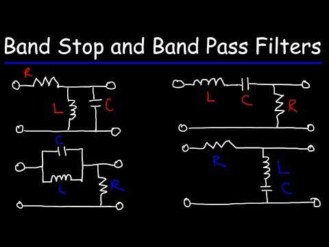
RLC Band Stop Filters and Band Pass Filters

Показать описание
This electronics video tutorial provides a basic introduction into RLC Band Stop Filters and RLC Band Pass Filters. An RLC Band Pass Filter blocks high level and low level frequencies while allowing mid level frequencies within a certain range to pass through. The RLC Band Stop works in reverse. It blocks mid level frequencies allowing high level and low level frequencies to pass through the circuit.
What Is a Diode?
Light Emitting Diodes:
Zener Diodes:
Varactor Diodes - Voltage Capacitors:
Generate Electricity With Crystals!
Boost Converter DC to DC Circuit:
________________________________
Simple Voltage Booster Circuit:
100,000V High Voltage Voltmeter:
Buck Converter Circuit:
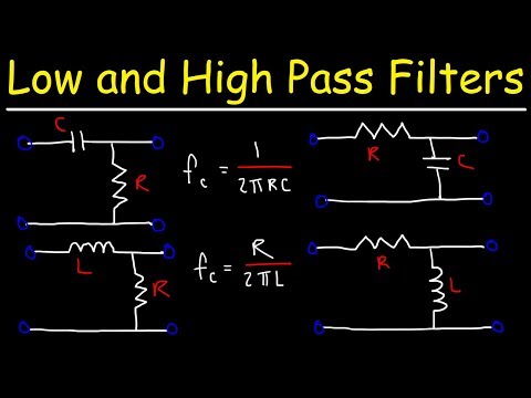
Low Pass and High Pass Filters:
RC Band Pass Filters:
______________________________
NPN and PNP Transistors:
Final Exams and Video Playlists:
Full-Length Videos and Worksheets:
What Is a Diode?
Light Emitting Diodes:
Zener Diodes:
Varactor Diodes - Voltage Capacitors:
Generate Electricity With Crystals!
Boost Converter DC to DC Circuit:
________________________________
Simple Voltage Booster Circuit:
100,000V High Voltage Voltmeter:
Buck Converter Circuit:
Low Pass and High Pass Filters:
RC Band Pass Filters:
______________________________
NPN and PNP Transistors:
Final Exams and Video Playlists:
Full-Length Videos and Worksheets:
 0:10:47
RLC Band Stop Filters and Band Pass Filters
 0:01:59
RLC - Band Pass, Band Stop Filters
 0:02:38
RLC Bandstop Filter
 0:12:56
Band Pass Filter and Band Stop Filter Explained
 0:06:43
How to design passive RLC band pass and band stop filters (4)
 0:18:28
Low Pass Filters and High Pass Filters - RC and RL Circuits
 0:01:15
Introduction to Band Pass and Reject Filters
 0:09:48
Filters - Passive Band-Stop Filter
 0:40:32
RLC Filters: The gateway to the world of filters
 0:01:42
Band Stop/Reject Filter by RC and RL circuit
 0:10:58
L14 5 1RigBand Reject filter
 0:01:34
RLC Band Reject Filter
 0:03:03
RLC band-stop filter help needed
 0:04:07
band stop filter in proteus
 0:04:27
RLC Box Filter-Topologies
 0:04:52
RLC Parallel Band Stop Filter
 0:01:25
Low pass, High pass, Band pass and Band stop filters explained
 0:11:27
77. Passive Filters (5): Band-stop filter
 0:03:07
Electronics: Band stop filter RLC circuit frequency response
 0:06:59
Designing band pass and reject filters
 0:08:48
FEC25D Band Pass Passive RLC Filter
 0:07:40
Passive RLC filters (low pass and Band-stop filter)
 0:07:20
RLC Series Band Stop Filter
 0:02:08
Introduction to Filters
Комментарии