filmov
tv
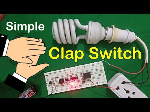
simple clap control home-automation.....#clapswitch

Показать описание
Sorry friends..... """":::: I am using circuit diagram is not correct in video..... please
check this link for correct and complete information ::::: """"
If you enjoy my videos please Subscribe!
check this link for correct and complete information ::::: """"
If you enjoy my videos please Subscribe!
 0:04:35
simple clap control home-automation.....#clapswitch
 0:08:19
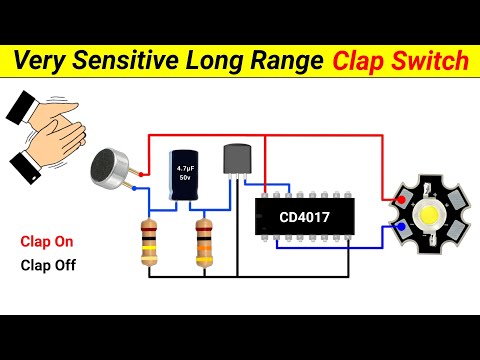
Simple Clap Switch circuit for Home-automation #clapswitch using Transistor & CD4017
 0:02:35
220V Simple Clap Switch Circuit Project | Make Clap Switch Circuit With Relay At Home
 0:05:52
how to make clap switch light on & off at home | Sound sensor| Smart Home Automation Arduino pro...
 0:06:09
clap switch circuit ||Simple clap control home automation || Deepak qd
 0:04:24
Simple clap control home automation clap switch
 0:02:43
How To Make Clap Switch at Home | Simple Clap Switch Circuit Using BC547 Transistor
 0:01:00
How To Make Clap Switch with Arduino and Sound Sensor | Arduino projects
 0:05:25
Simple Clap Switch circuit for Home Automation using CD4017
 0:08:17
How to make a Clap Switch using Arduino UNO!
 0:03:36
Arduino Clap Switch Using Sound Sensor | Easiest Way
 0:02:09
Simple clap switch control circuit
 0:03:31
Simple clap switch || ON and OFF lights using sound of clap
 0:08:35
How to make sensitive clap switch at home/DIY real clap switch/sound sensor switch
 0:04:36
Simple clap control home-automation ll simple clap switch circuit.
 0:03:18
How to make clap switch | simple home automation projects | BC547
 0:03:38
Control Fan & Light using Clap | Clap Switch using 4017
 0:10:28
How to make Voice Control Clap Switch circuit at home - JLCPCB
 0:06:07
How to make Smart Clap Switch using Arduino | DIY Arduino Projects
 0:06:27
Simple Clap Switch Circuit for Home Automation | Clap On/Off Switch
 0:04:02
How to make a Clap Switch using Arduino & Sound Sensor || Home automation project
 0:15:03
How to make a Clap Switch || using 4017 IC || Very Sensitive Clap Switch || Science Project
 0:04:19
How to make simple clap switch circuit||Simple clap control home automations#clapswitch#crazymrare
 0:06:25
Clap Switch circuit on Breadboard (Sound triggered LED) | Transistor + 555 timer projects
Комментарии